
Views: 0 Author: Site Editor Publish Time: 2026-08-13 Origin: Site


Oilfield environments present harsh operational realities. Silica dust, frac sand, caliche, and unpaved access roads generate massive particulate loads. These conditions rapidly overwhelm standard OEM engine filtration systems. Inadequate dust separation leads to frequent primary filter replacements. It accelerates premature engine wear and forces reduced Oil Change Intervals (OCI). Ultimately, poor filtration causes catastrophic unscheduled downtime that halts production entirely. Operating heavy machinery on a drilling pad means fighting a constant battle against airborne debris. Diesel engines consume thousands of cubic feet of air per minute. When that air contains high concentrations of abrasive silica, standard paper media filters plug up within hours. Mechanics spend excessive time swapping filters instead of performing preventative maintenance. Transitioning from passive filtration to active pre-cleaning systems is a necessary engineering upgrade. This shift protects capital assets, stabilizes maintenance schedules, and reduces overall operating expenses across your fleet.
Passive, single-stage filtration fails in high-particulate environments. Standard OEM filters rely entirely on media restriction to trap dirt. They clog quickly when exposed to heavy frac sand and caliche dust. Clogged filters severely impact combustion efficiency. They restrict intake air, causing engines to run rich. This imbalance elevates exhaust temperatures and increases overall fuel consumption. Turbochargers suffer immense stress as they work harder to pull air through blocked media. An air pre-cleaner for oilfield equipment intercepts this debris before it reaches the primary housing. Heavy equipment operators often notice a sharp drop in power when filters plug. The engine struggles to breathe, and fuel economy plummets. Standard paper elements simply lack the holding capacity for oilfield dust loads. You need a system that actively ejects dirt rather than just storing it in a paper element.
Frequent primary and secondary filter replacements carry massive hidden costs. You must calculate the true cost of these replacements accurately. Factor in the direct price of the filter elements. Add the hourly labor rate for mechanics performing the swap. Include the lost production revenue during equipment downtime. Changing filters twice a week on a stationary frac pump destroys operational efficiency. Active pre-cleaning extends filter life exponentially, keeping machinery running and mechanics focused on critical repairs. Consider the logistical nightmare of transporting hundreds of replacement filters to remote drilling sites. Storage space on a frac pad is limited. Every square foot matters. Reducing your filter consumption frees up valuable storage and reduces hot-shot delivery expenses.
| Cost Factor | Standard Filtration (Weekly) | With Active Pre-Cleaner (Monthly) |
|---|---|---|
| Primary Filter Cost | $150 x 4 = $600 | $150 x 1 = $150 |
| Labor (Mechanic Time) | 2 hours @ $100/hr = $200 | 0.5 hours @ $100/hr = $50 |
| Downtime Revenue Loss | $5,000 per hour x 2 = $10,000 | $5,000 per hour x 0.5 = $2,500 |
| Secondary Filter Swaps | 1 per month = $80 | 1 per 6 months = $13 (avg) |
Silica ingestion destroys diesel engines from the inside out. Micro-fine dust bypasses compromised filters and enters the combustion chamber. This abrasive material scores cylinder walls and degrades piston rings. Operators often force shorter Oil Change Intervals (OCI) to flush out these contaminants. Oil analysis serves as a vital diagnostic tool. Tracking silicon ppm levels reveals exactly how much dust bypasses your filtration system. High silicon levels indicate immediate filtration failure. Upgrading your intake protection directly lowers silicon counts and safely extends your OCI. When piston rings wear down from silica scoring, blow-by increases. Crankcase pressure rises, pushing oil out of seals and gaskets. You end up with a leaking, underperforming engine that requires a premature top-end rebuild. Stopping the dirt at the intake is the only way to prevent this chain reaction.
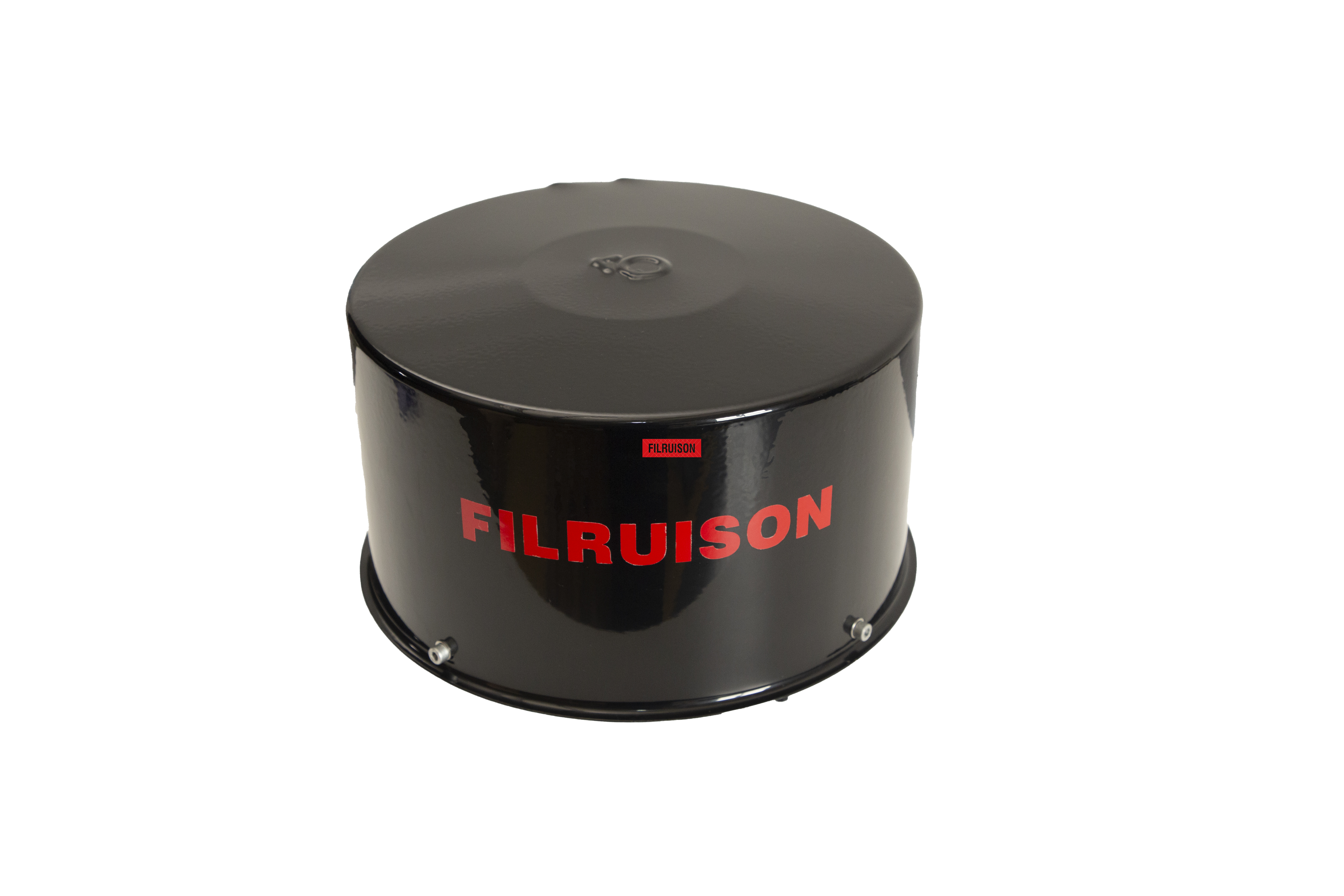
Cyclonic pre-cleaners utilize static vanes or impeller blades to generate centrifugal force. Incoming air spins rapidly inside the housing. This spinning action throws heavy particulates outward against the wall. The system then ejects the debris through a designated discharge port. Static models feature no moving parts, resulting in zero maintenance requirements. They handle heavy, abrasive dust exceptionally well. However, their performance depends entirely on intake air velocity. If engine RPM drops, separation efficiency decreases. These units work best on equipment that operates at a constant, high RPM. Generators and stationary pumps are prime candidates for static centrifugal units. The lack of moving parts makes them incredibly durable against the constant vibration of a diesel engine.
Aspirated systems actively pull dust from the pre-cleaner housing using exhaust gas flow. They connect to a venturi muffler or exhaust aspirator via a scavenge hose. The exhaust velocity creates a vacuum that continuously extracts separated particulate. These units deliver extremely high separation efficiency. They maintain active dust removal regardless of engine RPM or intake velocity. The trade-off involves a more complex installation process. Integrating the scavenge hose into the exhaust system requires precise routing and heat shielding. You must ensure the scavenge hose does not chafe against hot engine components. The venturi must be welded into the exhaust stack at the correct angle to generate maximum vacuum. When installed correctly, aspirated systems offer unmatched protection for variable-speed machinery.
Powered pre-cleaners use independent, electrically driven fans to separate dust. The motorized fan creates positive pressure inside the housing. This design guarantees consistent performance even when equipment idles for extended periods. Low engine RPM does not affect the separation efficiency. However, powered units introduce electrical components into high-vibration zones. Wiring harnesses and electric motors create potential failure points that require periodic inspection. You must route the wiring securely and use weather-tight connectors. The electric motor draws current from the equipment's alternator, so you must verify the electrical system can handle the additional load. Powered units excel on equipment that spends long hours idling in heavy dust, such as water trucks or site prep dozers.
Precise CFM matching dictates pre-cleaner success. Oversized pre-cleaners fail because they lack sufficient air velocity. Low velocity prevents the system from generating enough centrifugal force to eject heavy dirt. Undersized pre-cleaners create excessive intake restriction. This restriction starves the engine of oxygen, causing severe turbo lag and elevated exhaust gas temperatures. You must match the pre-cleaner exactly to the engine's maximum airflow demand. Do not guess the CFM based on the physical size of the intake pipe. A 6-inch pipe on one engine might flow 500 CFM, while a 6-inch pipe on a different engine flows 800 CFM. Always calculate the exact airflow requirements before ordering a unit.
Engineers must balance maximum debris removal with optimal engine aspiration. Many operators judge an oil exploration engine precleaner by the visible dust accumulating on the unit. This visual metric is highly misleading. High fractional efficiency targets micro-fine PM2.5 and PM10 silica particles. These invisible particles cause the most severe engine wear. Always demand ISO 5011 testing standards when evaluating manufacturer claims. ISO data proves actual separation efficiency across specific micron sizes. A pre-cleaner might catch 99% of large wood chips but let 50% of fine caliche dust pass right through. You need a unit engineered specifically for the fine, abrasive dust found on oilfield sites. Review the lab data before making a purchasing decision.
Oilfield machinery subjects components to extreme vibration and impact. Steel housings offer rugged protection but add significant weight to the intake stack. High-impact, glass-filled polymer housings provide excellent strength while reducing structural load. Evaluate the material's resistance to UV degradation. Consider how it handles extreme temperature fluctuations on the pad. The housing must also resist chemical exposure from drilling fluids and harsh degreasers. Metal units can rust if the powder coating chips. Polymer units will not rust, but they must be UV-stabilized to prevent them from becoming brittle in the harsh Texas or North Dakota sun. Choose a material that matches your specific environmental challenges.
You must calculate precise engine airflow to select the right unit. Use the standard formula: Engine Displacement x RPM x Volumetric Efficiency. Turbocharged engines require specific multipliers to account for forced induction. Naturally aspirated engines use different volumetric efficiency baseline numbers. Consult the engine manufacturer's data sheet to verify maximum CFM at full load. Never guess the airflow requirements.
Different dust types require specific specification adjustments. Fine, powdery caliche dust behaves differently than heavy, abrasive frac sand. Evaluate site-level dust collection dynamics. Stationary frac pumps often operate in tight clusters. The engine air intake interacts with ambient industrial air filtration systems on the pad. Position the intake stack to pull the cleanest possible air. An effective oilfield machinery dust separator adapts to these specific environmental challenges. If your equipment operates near a sand chief or blender, the dust load will be extreme. You might need to extend the intake stack higher into the air to escape the heaviest dust clouds. Always look at the prevailing wind direction and the layout of the pad when positioning your equipment.
Adding weight to the intake stack increases the risk of vibration-induced fatigue. Heavy pre-cleaner units can crack intake pipes or damage turbocharger connections. Implement strict bracing protocols during installation. Use flexible hump hoses to isolate engine vibration from the rigid intake piping. Support heavy units with custom fabricated brackets bolted directly to the machine frame. Do not rely on the factory air cleaner housing to support the weight of a large metal pre-cleaner. The constant shaking of a diesel engine will eventually tear the sheet metal. Build a sturdy cradle for the pre-cleaner and use heavy-duty T-bolt clamps on all silicone hose connections to prevent vacuum leaks.
Aftermarket installations must not void engine manufacturer warranties. Document air restriction gauge readings before installing the pre-cleaner. Record the readings immediately after installation under full load. This documentation proves the new system complies with OEM maximum restriction specifications. Keep these records in the equipment maintenance log to prevent warranty disputes. Most engine manufacturers allow a maximum intake restriction of 25 inches of water gauge. If your new pre-cleaner pushes the restriction to 20 inches right out of the box, you have very little room for the primary filter to load up with dirt. Ensure your total system restriction remains well below the OEM limit.
Even maintenance-free systems require basic visual inspections. Establish realistic intervals for checking debris screens and ejection ports. Inspect scavenge hoses for heat damage or vacuum leaks. Train operators to identify pre-cleaner blockages during their daily walk-arounds. Replace downstream primary filters based on restriction pressure measurements. Never replace them based on arbitrary calendar dates. A plugged ejection port will cause the pre-cleaner to fill with dirt, completely defeating its purpose. Operators should tap the housing lightly with a rubber mallet to dislodge any caked-on mud. Check the restriction gauge daily. If the gauge shows high restriction, inspect the pre-cleaner before assuming the primary filter is plugged.
An air pre-cleaner acts as a mandatory reliability upgrade for oilfield equipment operating in high-dust environments. Base your final selection on strict CFM matching and proven ISO-tested separation efficiency. Audit your current filter replacement frequencies to identify high-risk machinery. Calculate your fleet's required engine CFM using OEM data sheets. Consult with specialized filtration engineers to initiate a pilot test on your most problematic assets.
A: The ROI typically materializes within three to six months. Savings come from drastically reduced primary filter purchases, lower maintenance labor costs, and extended equipment uptime. Preventing premature engine wear also defers costly rebuilds.
A: No. A pre-cleaner acts as the first stage of defense. It removes heavy particulate and bulk debris, but the primary filter remains necessary to capture micro-fine dust and protect the engine internals.
A: Oversized units lack the intake air velocity required to generate sufficient centrifugal force. Without this force, the unit cannot separate heavy dirt, allowing debris to bypass the pre-cleaner and clog the primary filter.
A: It does not void the warranty if installed correctly. You must ensure the pre-cleaner does not exceed the OEM's maximum allowable intake restriction limits. Document restriction readings post-installation to maintain compliance.
A: Static centrifugal pre-cleaners rely entirely on intake air velocity to spin and eject dust. Aspirated pre-cleaners actively pull dust from the housing using a vacuum created by the engine's exhaust gas flow.
A: Track silicon ppm levels in your routine oil samples. High silicon indicates dirt bypassing the filtration system. A sharp drop in silicon levels after installing a pre-cleaner verifies successful dust separation and improved intake protection.
