
Views: 0 Author: Site Editor Publish Time: 2026-08-02 Origin: Site


In high-dust industrial and agricultural environments, standard air filters degrade rapidly, leading to accelerated engine wear and costly downtime. Installing an improperly sized Air Precleaner is a common operational failure. Operators often assume "bigger is better," but mismatched airflow dynamics either starve the engine of oxygen or fail to generate the centrifugal force required to separate particulates. Selecting the correct unit requires moving beyond basic displacement specs. This guide provides the technical framework for calculating precise engine airflow (CFM), evaluating restriction limits, using manufacturer selection calculators, and matching those metrics to the optimal engine intake precleaner for your specific application. We will break down the exact math, field measurements, and installation practices required to protect your heavy machinery from catastrophic dust ingestion.
Most precleaners rely entirely on the velocity of incoming air to function. This air velocity spins internal rotors or creates a cyclonic action inside the housing. Separation efficiency ties directly to maintaining specific air velocities. If the air moves too slowly, the centrifugal force drops. Without sufficient force, heavy dust particles will not separate from the airstream. They remain suspended and travel straight into the primary filter housing. In a rock quarry or a dry agricultural field, this means silica and chaff bypass the separation stage completely. The physics demand a tight correlation between the engine's suction and the internal geometry of the precleaner dome.
Installing an oversized unit is a frequent mistake made in the maintenance shop. When a precleaner is too large for the engine's airflow, intake velocity plummets. The precleaner fails to generate sufficient centrifugal force. Heavy dust bypasses the separation chamber entirely. This loads the primary filter at the exact same rate as if no precleaner were installed. You gain zero protection while adding unnecessary weight to the intake stack. A massive 10-inch housing on a small 4-cylinder diesel engine simply acts as a rain cap, offering no particulate separation value.
Exceeding a precleaner’s maximum CFM rating chokes the engine. Under-sizing causes severe air restriction. The engine struggles to pull enough oxygen for complete combustion. This leads to high intake restriction and increased pumping losses. You will experience elevated exhaust gas temperatures (EGTs) and severe turbocharger strain. Chronic under-sizing eventually destroys turbo seals and reduces overall engine lifespan. Operators will notice black smoke, sluggish throttle response, and frequent diesel particulate filter (DPF) regeneration cycles. The engine is essentially breathing through a straw.
A loose-fitting collar defeats the entire system. Degraded transition seals allow unfiltered air to enter the intake. You must route 100% of incoming airflow strictly through the precleaner intake dome. Any bypass leak allows heavy dust to skip the separation process. Inspect all clamps, rubber couplers, and mounting brackets regularly. System integrity determines your actual field efficiency. A pinhole leak downstream of the precleaner can dust an engine in a matter of hours, rendering the entire filtration setup useless.
You must determine your exact airflow requirements before selecting an engine intake precleaner. The baseline formula for a 4-cycle engine is straightforward. Multiply the Cubic Inch Displacement (CID) by the Maximum RPM, then divide by 3456. You must use the maximum governed RPM under load. Do not use idle or cruising RPM. This establishes the absolute peak airflow baseline your equipment will demand. For example, a 500 cubic inch engine running at 2200 RPM requires a baseline of 318 CFM. This is just the starting point before applying efficiency multipliers.
A standard 4-cycle engine does not operate at 100% efficiency. Volumetric Efficiency (VE) measures how completely the cylinders fill with air. Naturally aspirated diesel engines typically run at 0.80 to 0.85 VE. Turbocharged and aftercooled industrial engines push VE much higher. You must multiply your baseline CFM by the correct VE factor to get an accurate number. If you skip this step, your calculations will be dangerously inaccurate, leading to poor equipment selection.
| Engine Type | Typical Volumetric Efficiency (VE) |
|---|---|
| Naturally Aspirated Diesel | 0.80 - 0.85 |
| Turbocharged Diesel (Low Boost) | 1.10 - 1.30 |
| Turbocharged & Aftercooled (High Boost) | 1.50 - 3.00+ |
Forced induction drastically alters airflow requirements. Turbochargers force more air into the cylinders under pressure. You must apply a multiplier based on the maximum boost pressure. This calculates the pressure ratio. A turbocharged engine might consume 1.5 to 3.0 times more air than a naturally aspirated engine of the same displacement. Always account for maximum boost when sizing intake components. Check the OEM engine data plate or service manual to find the exact boost specifications for your specific machine.
Engines with fewer than four cylinders create severe intake pulsations. This uneven air draw can stall a precleaner during the intake stroke. You must apply compensation multipliers to prevent this. Multiply your calculated CFM by 2.1 for a 1-cylinder engine. Use 1.5 for a 2-cylinder engine. Use 1.2 for a 3-cylinder engine. This ensures the precleaner maintains momentum between intake strokes. Ignoring pulsation factors on small utility tractors or portable generators guarantees poor dust separation.
Manufacturer-provided interactive calculators help verify your manual math. Tools from major filtration brands allow you to input specific engine data. You will need to provide altitude, ambient temperature, and target restriction limits. These calculators adjust for air density changes. Always run your manual calculations first, then use digital tools to confirm your selection falls within safe operating parameters. High altitude operations require larger units because the air is less dense, forcing the engine to pull a higher volume to get the same mass of oxygen.
Look for the "sweet spot" when reviewing specifications. This is typically the middle 50% of a precleaner's rated CFM range. Do not size your unit right at the minimum or maximum limit. Variable RPM applications require a forgiving operating range. Wheel loaders and excavators constantly change engine speeds. A properly sized heavy equipment air precleaner maintains high efficiency across this entire variable load profile. If a unit is rated for 200-400 CFM, your target operating range should ideally sit between 250 and 350 CFM.
Every component added to an intake system creates drag. Initial restriction is measured in inches of water gauge (inH2O). You must establish the maximum acceptable added restriction. Keep total intake restriction well below the OEM maximum limits. High initial restriction robs the engine of power. Review the manufacturer's restriction curves before making a final selection. Most heavy diesel engines have a maximum allowable intake restriction of 20 to 25 inH2O. Your precleaner should ideally add no more than 2 to 4 inH2O to the system.
Not all efficiency claims are accurate. You must know how to read manufacturer testing data. Prioritize precleaners tested under strict ISO 5011 standards. This testing uses specific coarse and fine test dust. It ensures the performance data is verifiable and standardized across the industry. Reject products that only provide vague percentage claims without referencing standardized testing protocols. A claim of "99% efficient" means nothing if it was tested with gravel instead of standardized fine silica dust.
Matching the precleaner’s outlet neck to the existing air cleaner inlet pipe is critical. Measure dimensions accurately using calipers. Exclude external rubber seals or collar overlaps from your measurements. You need the actual metal-on-metal outer diameter (OD). Mismatched neck diameters create severe airflow bottlenecks at transition points. This turbulence reduces overall separation efficiency. If you must use an adapter, ensure it features a smooth, tapered transition rather than a hard, flat step.
Start by executing the manual CFM calculation discussed earlier. Factor in displacement, maximum governed RPM, volumetric efficiency, and forced induction multipliers. Apply pulsation factors if your engine has three cylinders or fewer. Verify your final number using an interactive modeling calculator to account for altitude and temperature variables. Write this number down; it is the foundation of your entire selection process.
Analyze how the machine actually works in the field. Generators and irrigation pumps operate at a constant high RPM. Excavators and skid steers operate at highly variable RPMs with frequent low idle periods. Variable RPM machines require a precleaner with a much wider effective operating range to maintain centrifugal force during idle. Constant RPM machines can be matched to a much tighter CFM tolerance.
Grab a set of calipers and a tape measure. Measure the outer diameter (OD) of the bare intake pipe. Check the available hood clearance. Ensure the installed unit will not block operator sightlines. Exclude all existing gaskets and rubber seals to obtain accurate hard-part measurements. Account for engine roll and vibration; the precleaner needs clearance so it does not strike the hood or cab during heavy load shifts.
Take your calculated CFM and compare it against the manufacturer’s operating curves. Ensure your machine's normal operating CFM lands within the high-efficiency zone. This zone is typically 50% to 85% of the maximum rated capacity. Avoid units where your CFM sits at the extreme low or high end of the curve. Request the actual performance graphs from the supplier rather than relying on a single printed number.
Evaluate your physical space and available power. Choose between static, active, or scavenged systems. If you have limited electrical capacity, stick to static units. If you idle frequently in heavy dust, consider an active motorized unit. Match the technology to your specific operational constraints. Consider the maintenance capabilities of your field crew when selecting complex scavenged systems.
| Technology Type | Mechanism | Primary Advantage | Trade-off |
|---|---|---|---|
| Static Centrifugal | Intake-driven suction spins internal rotors. | Highly reliable, minimal moving parts. | Efficiency drops significantly at low engine RPMs. |
| Motorized / Active | Powered by equipment electrical system. | 100% efficiency regardless of engine RPM. | Introduces electrical complexity and higher upfront costs. |
| Scavenged Systems | Exhaust gas velocity pulls dust out. | Continuous self-cleaning, zero maintenance. | Requires complex plumbing and specific exhaust setups. |
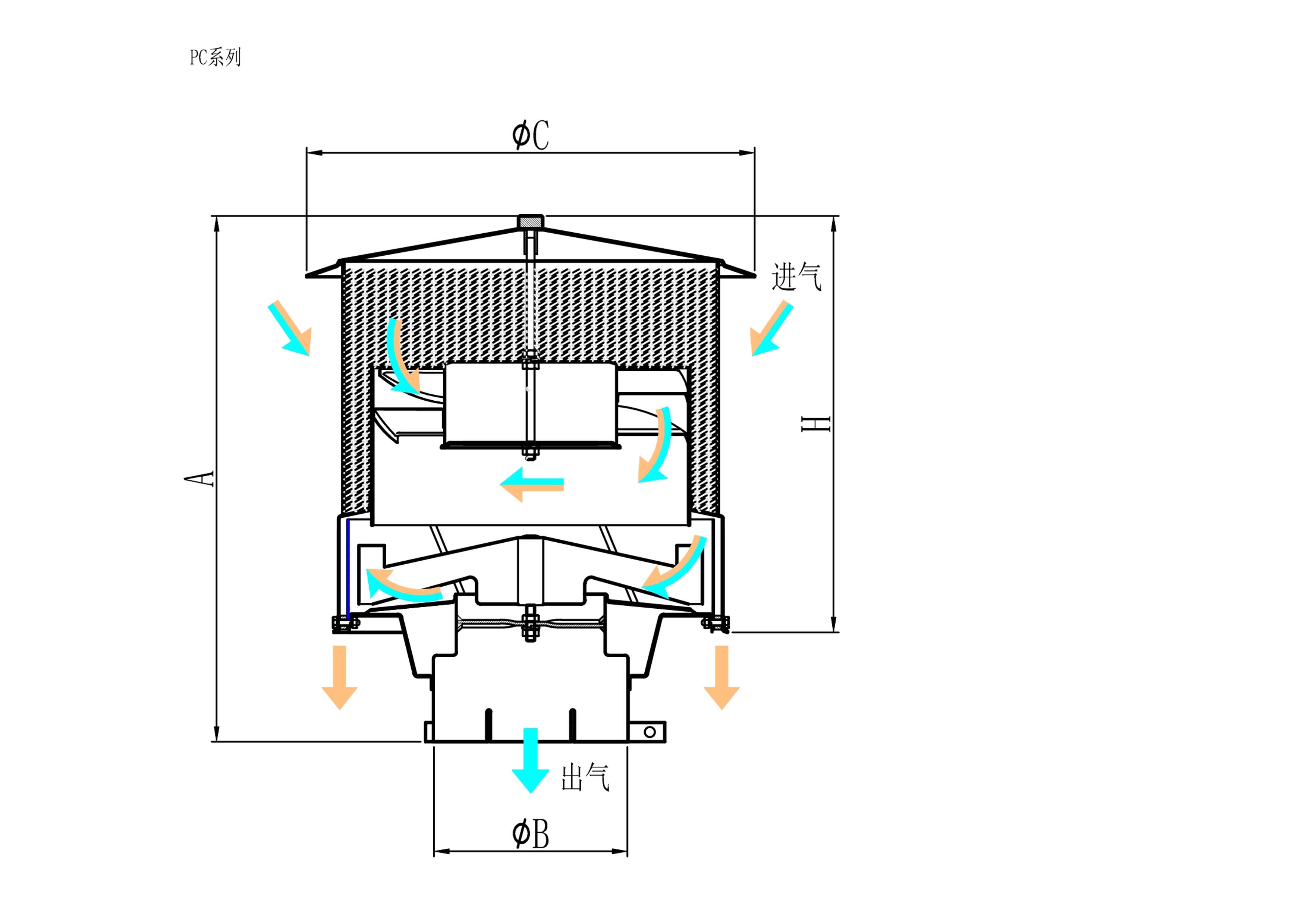
Traditional static units rely entirely on engine suction. The incoming air spins internal louvers or rotors to separate dust. They are highly reliable with minimal moving parts. However, there is a distinct trade-off. Because they rely on intake velocity, their separation efficiency drops significantly at low engine RPMs. They work best on equipment running at consistent, high engine speeds. Installation is generally straightforward, requiring only a heavy-duty clamp and a silicone coupler.
Active units use the equipment’s electrical system to power an internal fan. This maintains a constant rotor speed regardless of engine suction. The primary advantage is consistent separation efficiency. They deliver excellent protection for equipment that idles frequently in dusty zones. The trade-off involves higher upfront costs and added electrical complexity. You must ensure the alternator can handle the continuous amp draw. Wiring must be routed safely away from exhaust manifolds and pinch points.
Scavenged systems use exhaust gas velocity to pull separated dust out of the precleaner housing. The dust ejects directly through the exhaust stack. This offers continuous self-cleaning and requires virtually zero maintenance. The trade-off is installation difficulty. Scavenged systems require complex plumbing, specific exhaust configurations, and absolute system integrity to maintain the necessary vacuum pressure. A cracked scavenge line instantly destroys the system's effectiveness.
Properly sized precleaners have a substantial physical footprint. You must account for vibration and movement when mounting the unit. Ensure adequate clearance between the precleaner housing and the hood. Check that the added height does not obstruct the operator's field of vision. Heavy units may require additional support brackets to prevent stress fractures on the factory intake pipe. Always use high-quality, reinforced silicone couplers for the final connection. Standard rubber hoses degrade quickly under UV exposure and high under-hood temperatures.
A: No. Oversizing reduces the intake air velocity inside the housing. Without sufficient velocity, the unit cannot generate the centrifugal force needed to separate heavy dust particles from the airstream.
A: A turbocharger forces compressed air into the engine, drastically increasing the volume of air consumed. You must apply a multiplier based on maximum boost pressure to calculate accurate airflow demands.
A: Engines with three cylinders or fewer create uneven air draw, known as intake pulsation. This pulsation can stall the precleaner's rotor. A multiplier ensures the unit is sized to maintain momentum.
A: Initial restriction is the drag added to the intake system by installing the precleaner, measured in water gauge (inH2O). High restriction starves the engine of oxygen and increases exhaust temperatures.
A: Active precleaners maintain constant separation efficiency regardless of engine RPM. They are superior for equipment that idles frequently in heavy dust, though they require electrical wiring and draw continuous amperage.
A: Inspect all clamps, brackets, and silicone couplers every 250 hours during standard preventative maintenance. Vibration can loosen hardware, creating bypass leaks that allow unfiltered dust directly into the engine.
