
Views: 0 Author: Site Editor Publish Time: 2026-08-07 Origin: Site


Heavy equipment in mining, agriculture, and demolition operates in brutal conditions. Airborne dust destroys engines fast. Standard air filters fail quickly in these environments. You end up with clogged filters, premature wear, and dead machines on the site. Adding a pre-filtration stage is standard practice for fleet managers. But sizing it wrong is a massive failure point. Mechanics often size units based on visual fit or intake pipe diameter. They ignore actual engine airflow requirements. This mistake causes catastrophic engine restriction or zero dust separation. We need a technical framework to fix this. You must evaluate, calculate, and select the right unit based on hard data. This maximizes primary filter life without choking the engine. Proper sizing keeps your iron running and out of the shop.
Understanding the physics behind a Static Vane Air Precleaner is critical for proper application. These devices rely on centrifugal force to separate heavier-than-air particles from the incoming airstream. This happens before the dirt reaches the primary filter element. Ambient air is drawn into the unit. It passes through a series of stationary, angled vanes. These vanes force the linear airflow into a high-speed rotational vortex. Dust, dirt, chaff, and snow carry more mass than the air itself. The centrifugal force generated by this vortex pushes the heavier particulate matter toward the outer wall of the housing. Once the debris reaches the perimeter, it is safely expelled through a designated discharge port. Only the purified air continues down the intake pipe toward the engine.
The entire separation process relies exclusively on the suction generated by the engine. There are no external power sources. You will not find auxiliary fans driving the vortex. The efficiency of the centrifugal separation is directly proportional to the velocity of the air moving through the stationary vanes. If the air moves too slowly, the vortex lacks kinetic energy. It cannot push heavy particles to the outer wall. Debris bypasses the ejection port and travels directly into the primary filter. If the air moves too quickly, the system creates an aerodynamic bottleneck. Maintaining the precise air velocity required for optimal vortex generation is non-negotiable. This is why accurate sizing matters on every single machine.
Equipment managers typically choose between static vane models and dynamic turbine-style precleaners. Static designs feature zero moving parts. They utilize fixed internal geometry to manipulate airflow. This makes them inherently maintenance-free and highly durable. Dynamic precleaners incorporate internal spinning rotors. Incoming airflow drives these impellers to actively sweep debris out of the housing. Dynamic models can be effective in light dust. However, static designs are vastly preferred in highly abrasive environments like rock quarries or demolition sites. Moving parts are susceptible to bearing failure. They suffer imbalance from uneven dust accumulation. They experience mechanical jamming when exposed to large debris. Static units eliminate these mechanical failure points entirely. They ensure continuous protection without requiring scheduled maintenance.
| Feature | Static Vane Precleaner | Dynamic/Turbine Precleaner |
|---|---|---|
| Moving Parts | None | Spinning rotor/impeller |
| Maintenance | Zero maintenance required | Requires bearing checks and cleaning |
| Durability in Heavy Debris | Excellent (no jamming) | Poor (prone to mechanical jamming) |
| Vibration Tolerance | High | Moderate (can cause rotor imbalance) |
Implementing a properly sized unit yields immediate improvements in equipment reliability. A well-engineered static system captures and ejects 85% to 90% of ISO coarse test dust. This happens before it ever reaches the primary filter housing. In practical field applications, this level of separation efficiency extends primary filter life by three to eight times. The exact extension depends on specific environmental conditions and the baseline dust load. This high level of pre-filtration prevents sudden spikes in intake restriction. Standard filters load up rapidly during heavy earthmoving operations. A good precleaner maintains consistent engine performance throughout the entire shift.
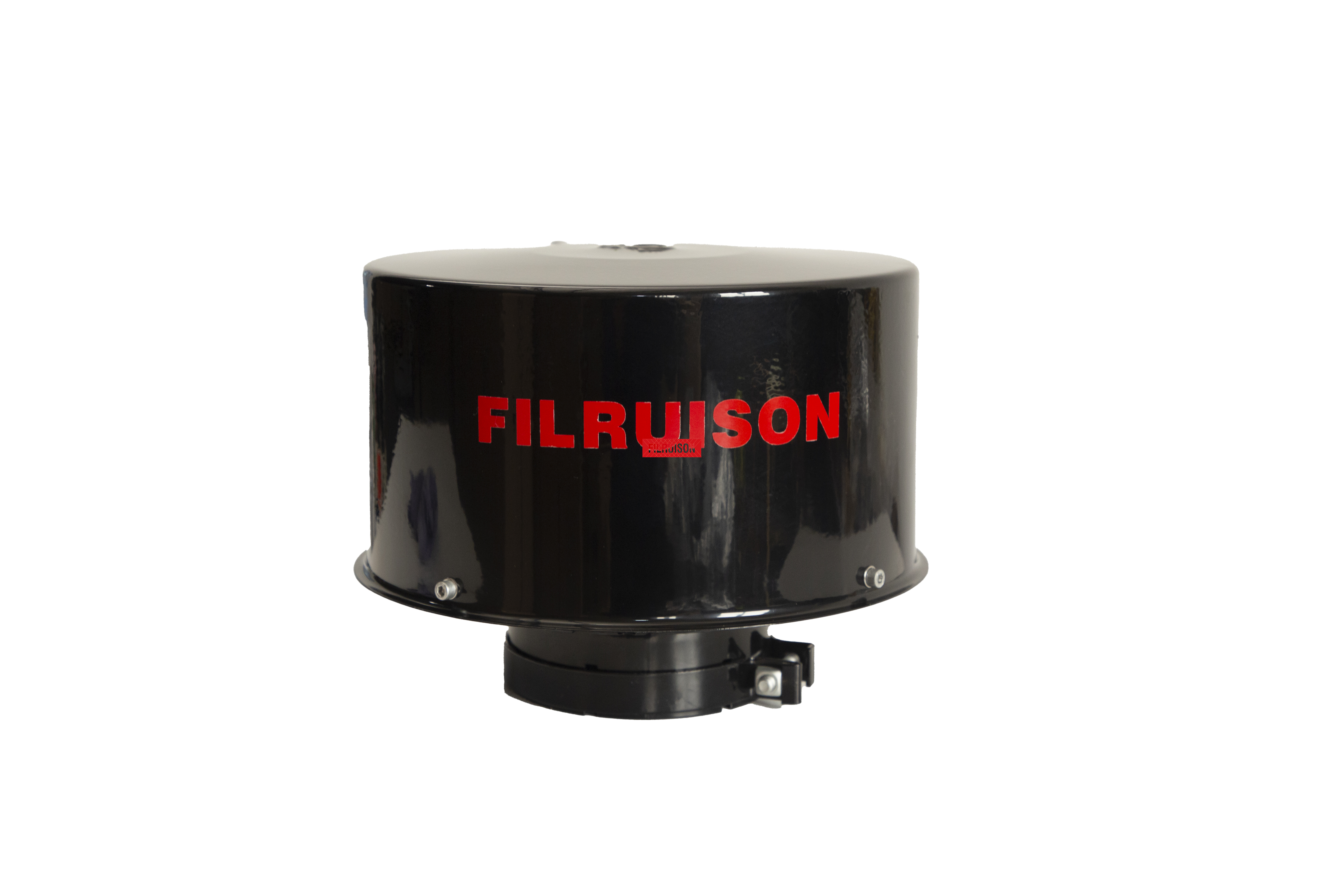
The most destructive mistake made during precleaner selection is matching the unit to the existing intake pipe diameter. An intake pipe measuring five inches in diameter might connect to a small, high-revving engine. It might also connect to a large, slow-turning diesel block. The physical pipe size offers absolutely no indication of the actual volume of air the engine consumes. Selecting a precleaner based solely on pipe diameter completely compromises air velocity. If the chosen unit is designed for a much higher airflow than the engine produces, the centrifugal vortex fails to form. The device becomes useless. Sizing must always be based on the engine's maximum Cubic Feet per Minute (CFM) requirement.
To determine the correct size for an engine intake static precleaner, you must calculate the maximum airflow the engine demands under full load. The standard formula for four-cycle engines requires knowing the engine displacement in cubic inches and the maximum governed RPM.
The base calculation assumes 100% volumetric efficiency. This is not accurate for real-world engines. You must apply a volumetric efficiency multiplier. Naturally aspirated engines typically operate at roughly 85% efficiency. They require a multiplier of 0.85. Turbocharged and aftercooled engines force significantly more air into the cylinders. They require multipliers ranging from 1.5 to 3.0 or higher. This depends on the specific boost pressure generated by the turbocharger. Consulting the engine manufacturer's specification sheet for the exact maximum CFM rating is always the most accurate method.
| Engine Aspiration Type | Typical Volumetric Efficiency Multiplier |
|---|---|
| Naturally Aspirated | 0.85 |
| Turbocharged (Low Boost) | 1.50 - 1.80 |
| Turbocharged & Aftercooled | 2.00 - 3.00+ |
Field operating conditions heavily influence the target CFM range. Equipment operating continuously at high RPMs consistently draws air near maximum CFM ratings. Think of agricultural combines or stationary generators. Variable-load machinery experiences frequent fluctuations in engine speed and airflow demand. Wheel loaders and excavators fit this profile. When sizing for variable-load applications, select a precleaner where the engine's average operating CFM falls squarely in the middle of the precleaner's optimal performance range. High-altitude operations and extreme ambient temperatures alter air density. This impacts the actual mass of air entering the intake. The volumetric CFM remains relatively constant. However, reduced air density at high altitudes may require slight adjustments. You must ensure the vortex maintains sufficient kinetic energy to separate fine dust particles.
Installing an undersized precleaner creates a dangerous operational paradox. The internal volume of the precleaner is small relative to the engine's airflow demand. The air velocity through the stationary vanes accelerates dramatically. This high velocity generates a powerful centrifugal vortex. You get exceptionally high dust separation efficiency. However, this separation comes at an unacceptable mechanical cost. Forcing a massive volume of air through a restrictive, undersized housing acts as a severe choke point. The engine must work exponentially harder to pull the required air through the restriction. This creates a high vacuum condition in the intake tract.
The operational consequences of this high restriction are severe. The engine experiences air starvation. This leads to incomplete combustion. Operators notice a sharp increase in fuel consumption. They feel a significant drop in available horsepower. The lack of sufficient airflow causes exhaust gas temperatures to spike. This places extreme thermal stress on turbochargers and exhaust valves. In severe cases, the high vacuum pulls dirt right through the primary filter media. It can cause the filter element to collapse entirely. This leads to catastrophic engine dusting and immediate failure on the job site.
Installing an oversized unit presents a completely different set of mechanical failures. Suppose a precleaner rated for 1,000 CFM is installed on an engine that only draws 400 CFM. The air velocity through the internal vanes drops significantly below the required operational threshold. The engine simply does not generate enough suction to accelerate the air through the large housing. The system fails to generate a strong centrifugal vortex.
The kinetic energy is too low to push heavy dirt and rock particles to the outer ejection wall. Abrasive debris simply drifts through the precleaner housing. It gets pulled directly down the intake pipe. The precleaner essentially becomes a useless hood ornament. The primary filter loads with dust at the exact same rate as if no precleaner were installed. This completely negates the purpose of the investment. It leaves the engine vulnerable to rapid filter blinding in heavy dust conditions. You waste money and gain zero protection.
The physical installation geometry plays a massive role in the overall success of a fixed vane dust separator. The distance between the precleaner and the primary filter housing must be carefully managed. Mounting the unit high above the equipment cab helps access cleaner ambient air. However, excessively long runs of intake piping introduce significant aerodynamic drag. Every foot of pipe and every elbow fitting adds restriction to the system. Installations should prioritize short, straight runs wherever possible. This maintains laminar airflow. If long routing is unavoidable, the diameter of the connecting pipe must be properly sized. This minimizes friction losses without causing velocity drops that allow suspended dust to settle inside the pipe.
Static vane units are highly dependent on proper mounting orientation. Some designs tolerate slight angles. Vertical mounting is universally recommended. Gravity assists in the ejection of separated heavy particles through the discharge louvers. Mounting a static vane air precleaner horizontally disrupts the vortex dynamics. Heavy debris pools inside the housing rather than ejecting cleanly. Heavy industrial machinery generates intense structural vibration. The precleaner must be securely mounted using heavy-duty brackets. Use vibration isolators where necessary. Rigidly mounting a heavy precleaner directly to a thin intake pipe without supporting brackets leads to metal fatigue. You will get cracked pipes and massive unfiltered air leaks downstream.
Sizing must be based on CFM rather than pipe diameter. It is highly common for the correctly rated precleaner to have a different base diameter than the machine’s existing intake stack. This requires the use of adapters or pipe reducers. When stepping up or stepping down the pipe size, the transition must be smooth and gradual. Using harsh, flat-faced reducers creates severe air turbulence. Sharp 90-degree elbows immediately below the precleaner add massive restriction. Always utilize smooth, tapered silicone or rubber transition hoses. This ensures clean aerodynamic flow from the precleaner base into the intake piping.
Certain applications present unique installation challenges. Underground mining equipment, skid steers, and compact track loaders feature low-profile hoods. They have extremely tight engine compartments. This leaves minimal space for external intake modifications. In these confined environments, specialized low-profile static precleaners are required. Equipment operating in sensitive indoor environments faces unique debris types. Waste recycling facilities deal with plastic film, paper shreds, or fine lint. The precleaner must be evaluated for its ability to eject these specific materials without clogging the discharge ports.
The engineering approach differs significantly between replacing a failed factory unit and designing a custom retrofit. OEM systems are generally engineered for average operating conditions. When a machine moves into an exceptionally harsh environment, the OEM precleaner often proves inadequate. Transferring a standard wheel loader into a high-silica rock quarry requires an upgrade. Retrofitting requires a complete baseline audit of the engine's maximum CFM. You must check existing intake restriction levels and the specific type of ambient dust. Custom retrofits often require fabricating new mounting pedestals. You must upgrade the intake piping to handle the increased weight and airflow dynamics of a heavy-duty industrial precleaner.
The operational success of any intake protection strategy relies entirely on precise, data-driven sizing. Selecting a unit based on physical appearance or pipe diameter guarantees system failure. You will either suffocate the engine or get inadequate dust separation. By strictly adhering to CFM-based calculations, maintenance teams ensure optimal vortex generation. This maximizes filter life and protects critical engine components from abrasive wear.
A: It is a maintenance-free mechanical device installed at the beginning of an engine's air intake system. It uses stationary, angled fins to force incoming air into a high-speed vortex, utilizing centrifugal force to eject heavy dust, dirt, and debris before it can reach and clog the primary engine air filter.
A: Calculate the base CFM by multiplying the engine displacement in cubic inches by the maximum RPM, then dividing by 3456. For naturally aspirated engines, multiply the result by 0.85. For turbocharged engines, multiply the base number by 1.5 to 3.0, depending on the specific turbo boost pressure.
A: All pre-filtration devices add a minor baseline restriction to the intake system. However, a correctly sized unit keeps this restriction well below the engine manufacturer's maximum allowable limits. An undersized unit, conversely, will choke the airflow and cause severe, damaging restriction.
A: No. Sizing based on pipe diameter is a critical error. The physical size of the pipe does not correlate to the volume or velocity of air the engine consumes. Proper centrifugal separation requires specific air velocities that can only be achieved by sizing strictly according to the engine's CFM demand.
A: It should be mounted as close as practical while still accessing clean ambient air. While elevating the unit reduces initial dust intake, excessively long pipe runs or multiple elbows create aerodynamic drag and pressure drops. Always prioritize short, straight piping runs to maintain laminar airflow.
A: While some units tolerate slight angles, vertical mounting is strongly recommended. Gravity plays a crucial role in pulling the separated heavy particles down and out through the ejection louvers. Horizontal mounting can disrupt the vortex and cause debris to pool inside the housing.
A: Static vane models have zero moving parts, relying entirely on fixed internal geometry and engine suction to create a vortex, making them highly durable and maintenance-free. Dynamic precleaners use internal spinning impellers driven by airflow to actively sweep out dust, which introduces mechanical parts that can wear out or jam.
