
Views: 0 Author: Site Editor Publish Time: 2026-08-06 Origin: Site


Operating heavy-duty equipment in high-dust environments presents a harsh reality: premature engine wear and frequent primary filter replacements are direct results of inefficient pre-filtration. When loaders, excavators, and agricultural tractors operate in quarries or dry fields, the engine ingests massive amounts of airborne debris. While installing an engine intake static precleaner is standard practice across these industries, improper inlet orientation can severely degrade centrifugal separation efficiency. It can introduce unacceptable intake restriction or cause clearance and mounting failures that compromise the entire intake system.
Evaluating which inlet orientation—vertical, horizontal, or modified U-shaped—maximizes performance requires understanding equipment constraints, airflow dynamics, and contaminant types. This guide provides a technical framework for aligning your pre-filtration hardware with operational realities. By matching the physical installation to the specific airflow demands of the engine, operators ensure optimal protection, maintain proper air-to-fuel ratios, and extend the service life of the primary paper elements.
Successful pre-cleaning typically achieves 70-85% separation of mass before contaminants reach the primary filter. Airflow geometry forms the foundation of this success. If the orientation disrupts the incoming air, the separation efficiency drops rapidly. This forces the primary filter to handle a heavier load, reducing service intervals and increasing the risk of dust bypassing the filter media. The goal is to remove the bulk of the heavy particulate matter before it ever enters the main air housing. Achieving this requires a stable, uninterrupted flow of air entering the precleaner assembly.
When evaluating success, technicians look at the restriction gauge on the main filter housing. If a precleaner is installed but the restriction gauge still trips frequently, the precleaner is either undersized, improperly oriented, or suffering from turbulent airflow at the inlet. The geometry of the intake piping directly dictates how well the precleaner can establish the necessary centrifugal vortex.
Air is drawn through stationary, angled vanes, creating a high-velocity vortex inside the housing. Centrifugal force drives heavier-than-air particles to the outer wall of the chamber. These particles are then ejected via a scavenge system or louver, leaving cleaner air to flow down the center tube into the engine intake. The angle and spacing of these vanes are engineered for specific airflow ranges.
Because the vanes do not move, the system relies entirely on the velocity of the incoming air to generate the centrifugal force. If the air enters at an angle or is turbulent due to a sharp bend immediately before the vanes, the vortex becomes lopsided. A lopsided vortex allows dust to bypass the ejection port and travel straight down the center tube, defeating the purpose of the device.
A static vane air precleaner relies entirely on engine draw rather than moving parts. Orientation changes how gravity interacts with the centrifugal vortex. At lower engine RPMs, where vacuum draw is weakest, gravity plays a larger role in moving separated dust toward the ejection port. If the unit is mounted horizontally, the centrifugal force must be strong enough to keep the dust suspended against the outer wall until it reaches the ejection slot. If the RPM drops, the dust simply falls to the bottom of the housing, causing localized wear and potential re-entrainment.
This interplay means that sizing the precleaner correctly is even more critical when deviating from a standard vertical installation. An oversized precleaner mounted horizontally will fail to generate enough velocity at idle to eject the dust, leading to rapid accumulation inside the housing.
Static vane designs differ significantly from dynamic, impeller-driven, or powered turbine systems. Static systems are highly durable and maintenance-free because they have no bearings to wear out or rotors to jam. However, because they lack an active mechanical expeller, they are far more sensitive to inlet orientation and gravity alignment.
| Feature | Static Vane Systems | Dynamic/Turbine Systems |
|---|---|---|
| Moving Parts | None | Internal rotor/impeller and bearings |
| Orientation Sensitivity | High (relies on gravity and airflow velocity) | Low (rotor actively ejects debris) |
| Maintenance Requirements | Visual inspection, occasional clearing of large debris | Bearing replacement, rotor cleaning |
| Durability in High Vibration | Excellent (solid construction) | Moderate (bearings can fail under extreme vibration) |
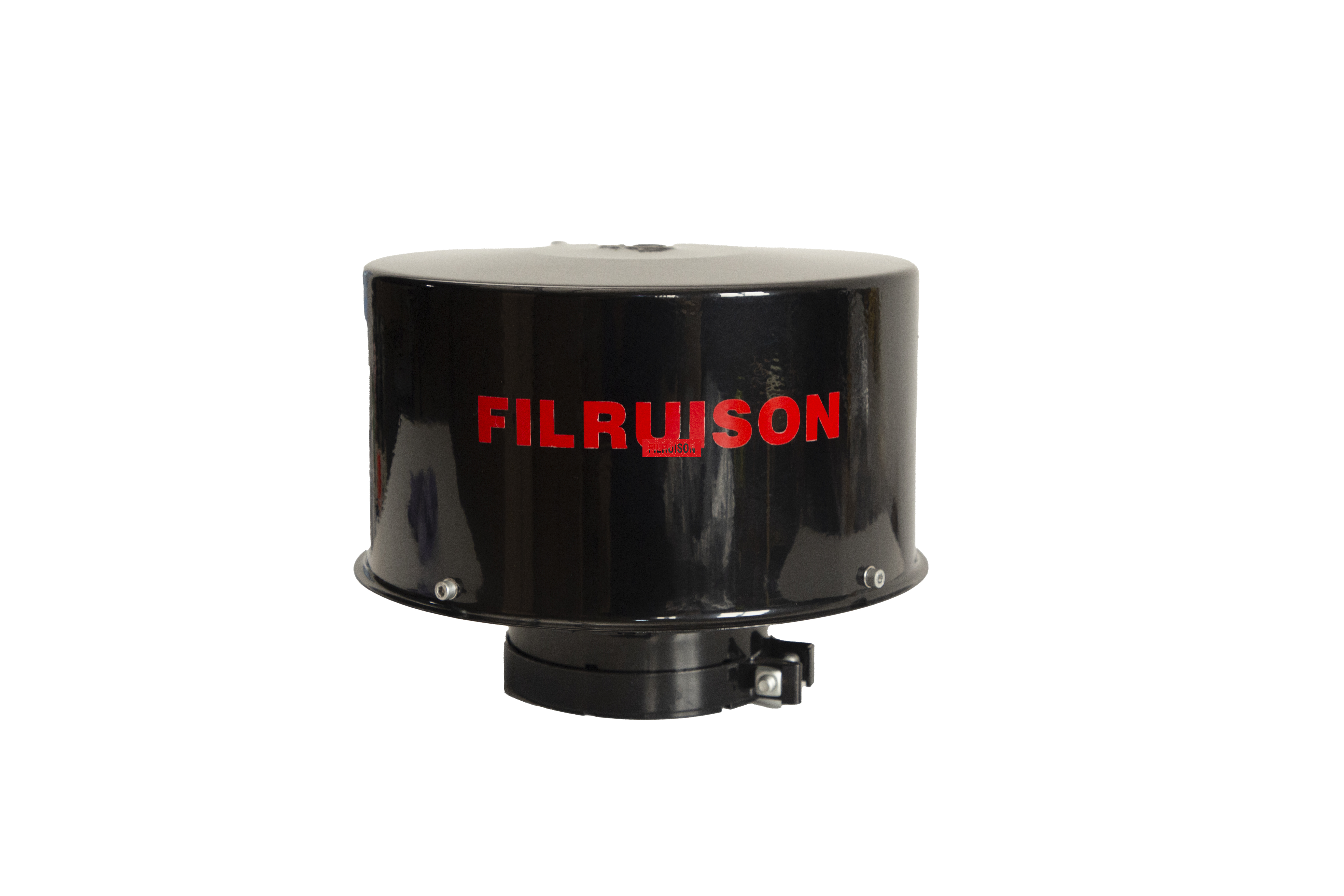
Air enters from the top, moves downward through the vanes, and exits the bottom into the intake stack. This orientation is highly efficient for heavy dust because gravity assists the downward flow of separated particulates toward the ejection port. The natural downward path means that even at low idle, heavy dirt particles are encouraged to exit the housing rather than pooling inside.
This setup is perfect for handling large fibrous contaminants alongside heavy dust when fitted to an extended cleaner inlet stack. Standard applications include heavy construction machinery, agricultural tractors with open canopies, and stationary generators. The vertical stack places the intake high above the primary dust cloud generated by the equipment's tires or tracks, providing a cleaner baseline of air.
However, vertical mounting increases overall vehicle height. Equipment operating in forestry applications or areas with low overhead clearances may suffer from stack damage. Furthermore, vertical intakes are susceptible to direct rain or snow ingress if not fitted with a proper rain cap or engineered louver system designed to shed water outward.
Air enters horizontally, passes through the vanes, and continues horizontally or takes a 90-degree downward turn post-separation. In this configuration, centrifugal force must overcome gravity to keep particles suspended in the outer vortex until they reach the ejection port. This requires precise CFM matching to ensure the air velocity remains high enough across all engine operating speeds.
Use cases include cab-over trucks, enclosed engine bays, and agricultural equipment with strict overhead clearance limits. When equipment cannot accommodate a tall vertical stack, side-draft mounting allows the precleaner to sit flush against the hood or tucked inside a protective compartment.
The limitations include a higher risk of particle re-entrainment if airflow drops. If the engine idles for extended periods, the centrifugal force weakens, and gravity pulls the abrasive dust downward. This causes uneven wear on the lower half of the housing. Over time, this localized abrasion can wear a hole straight through the plastic or metal casing, requiring complete replacement of the unit.
Adapting straight-down intakes using U-shaped hoses allows mounting the precleaner upright, or sometimes mounting the precleaner inverted. U-shaped routing introduces significant turbulence and pressure drop before the air even reaches the primary filter. Every bend in the intake piping forces the engine to work harder to draw in the same volume of air.
This configuration is common when retrofitting compact equipment where the factory intake points straight down, requiring specialized aftermarket elbow adapters. Skid steers and compact track loaders often have extremely cramped engine compartments, forcing technicians to route the intake piping through tight spaces using multiple silicone elbows.
Inverted static precleaners often fail because ejection ports are designed for gravity-assisted downward or horizontal ejection. When mounted upside down, the dust must be pushed upward against gravity to exit the louver. This rarely works efficiently, leading to rapid clogging. U-bends require up-sizing the piping to mitigate restriction. If a 3-inch pipe is standard, a U-bend configuration might require stepping up to a 4-inch pipe through the bend to maintain the required airflow volume without exceeding restriction limits.
Heavy, abrasive dust found in mining or quarrying requires a vertical orientation to prevent excessive housing wear. Silica dust and crushed rock act like sandpaper inside the precleaner housing. By mounting the unit vertically, gravity helps pull this abrasive material out of the ejection port quickly, minimizing the time it spends scouring the inner walls.
Fibrous material and crop chaff encountered in agriculture require specific wide-vane spacing and specialized mounting angles to prevent clogging. Combine harvesters operating in dry wheat or soybeans generate massive amounts of lightweight, stringy debris. A standard fixed vane dust separator can quickly become choked if the vanes are too close together. The orientation must allow for easy visual inspection so operators can clear chaff buildup during routine field stops.
Calculating engine CFM requirements is the most critical step before selecting and orienting a precleaner. The formula involves multiplying engine displacement by RPM, dividing by 3456, and factoring in volumetric efficiency. Once the CFM is known, you must measure baseline intake restriction and calculate the added restriction of 90-degree elbows or U-bends required for specific orientations.
Exceeding the manufacturer's restriction limits will degrade engine performance, increase exhaust gas temperatures, and cause the engine to run rich, leading to excessive soot production and potential damage to emissions control systems.
Horizontal or offset vertical orientations place higher stress on intake piping and clamps due to equipment vibration, known as the cantilever effect. A heavy precleaner mounted at the end of a long horizontal pipe acts as a lever, amplifying engine vibrations and transferring that stress directly to the rubber intake boots and hose clamps.
Structural supports, brackets, and heavy-duty T-bolt clamps are necessary for precleaners mounted on extended horizontal or vertical stack arms to prevent fatigue failures. Relying solely on the rubber intake hose to support the weight of the precleaner will inevitably lead to torn boots, massive vacuum leaks, and catastrophic engine dusting. Always fabricate rigid steel or aluminum brackets that tie the precleaner housing directly to the machine's frame or a solid mounting point on the engine block.
Placing a sharp bend immediately before the precleaner disrupts the uniform airflow required for the fixed vanes to create a balanced vortex. When air rushes around a tight corner, it speeds up on the outside of the bend and slows down on the inside. This uneven velocity profile hits the static vanes and creates a distorted centrifugal field.
Mandate a minimum straight-pipe run, typically 2 to 3 times the pipe diameter, before the precleaner inlet. If you are using a 4-inch intake pipe, you need at least 8 to 12 inches of straight, uninterrupted pipe immediately before the air enters the precleaner. This allows the airflow to stabilize and distribute evenly across the entire face of the static vanes, ensuring maximum separation efficiency.
Complex routing to achieve a specific orientation starves the engine of air. Every 90-degree elbow adds restriction equivalent to several feet of straight pipe. If an installation requires snaking the intake hose through a tight engine bay with multiple bends, the cumulative restriction can easily exceed the engine's safe operating parameters.
Use restriction gauges during installation testing. Plumb a water manometer or a high-quality dial vacuum gauge into the intake tract just before the turbocharger or intake manifold. Run the engine under full load and verify that the vacuum reading remains well below the manufacturer's limit. Upsize the ducting diameter for U-shaped bends to slow the air down through the curve, which significantly reduces the pressure drop.
Upward-facing ejection ports in modified orientations can collect water, leading to freezing and cracking of the housing. When equipment is washed down or left outside in heavy rain, water can pool inside the precleaner if the ejection louver is not positioned correctly.
Ensure ejection louvers are oriented at the lowest point of gravity, regardless of the overall inlet orientation. If mounting the unit horizontally, rotate the housing so the ejection slot points straight down toward the ground. This allows any ingested water to drain out naturally. In freezing climates, trapped water will expand as it turns to ice, easily shattering plastic housings and destroying the precleaner.
Certain orientations restrict physical and visual access, leading to neglected maintenance and blocked vanes. Tucking a precleaner deep inside a loader's engine compartment might solve clearance issues, but if the operator cannot see it, they will not clean it. In agricultural settings, chaff and leaves can bridge across the static vanes, completely choking off the air supply.
Design the mounting configuration to allow easy removal for cleaning, or position the ejection port where it can be visually checked during daily walkarounds. Use quick-release clamps rather than bolted flanges where possible. The easier it is for a technician to access the unit, the more likely it is that the precleaner will receive the necessary attention during routine preventative maintenance schedules.
The orientation flexibility of a Static Vane Air Precleaner differs from powered dynamic centrifugal systems. While static vanes are highly durable and maintenance-free, their reliance on engine vacuum makes them more sensitive to suboptimal inlet orientations than motorized or active-scavenge systems. An active system uses a spinning rotor to physically throw dirt out of the housing, meaning it can operate efficiently even if mounted at odd angles or subjected to turbulent inlet air.
However, the simplicity and ruggedness of static systems make them the preferred choice for extreme environments where moving parts would quickly fail. Proper orientation is critical to extracting maximum value from a static system. By respecting the physics of airflow and gravity, technicians can achieve separation efficiencies that rival much more complex and expensive dynamic systems, all without adding any maintenance burden to the equipment operator.
Vertical orientation remains the gold standard for static vane precleaners due to gravity assistance and minimal piping restriction. Horizontal and U-shaped orientations are viable if engineered correctly. Selection relies on four pillars: Engine CFM requirements, physical clearance constraints, contaminant profile, and maximum allowable intake restriction. Taking the time to properly calculate airflow and design a rigid, low-restriction mounting system ensures the engine receives clean air under the harshest conditions.
A: Yes. Orientation impacts how gravity interacts with the centrifugal vortex. Vertical setups generally offer the highest separation efficiency for heavy dust as gravity assists the evacuation path, pulling dirt down and out of the ejection port.
A: Yes, but it introduces additional intake restriction and turbulence. You must ensure the total restriction remains below the engine's maximum limit, keep a straight run of pipe before the vanes, and upsize the hose diameter to reduce pressure drop.
A: Typically between 1 to 3 inches of water gauge, depending on the specific model, the operational CFM of the engine, and the complexity of the inlet orientation and associated piping.
A: Inverted orientations are generally not recommended for heavy dust. Gravity works against the ejection port design, forcing the system to push dirt upward, which leads to poor separation and rapid housing wear.
A: Ensure the ejection louver is positioned at the lowest point of gravity. Rotating the housing so the slot points downward allows water to drain naturally rather than pooling inside and risking freeze damage.
A: An oversized unit will not generate enough air velocity to create a strong centrifugal vortex. Dust will simply pass through the vanes and enter the primary filter, rendering the precleaner ineffective.
