
Views: 0 Author: Site Editor Publish Time: 2026-08-04 Origin: Site


Determining the right particle loads for a centrifugal air precleaner comes down to understanding particle mass and operating environments. These devices excel at separating heavy, coarse debris like sand, gravel dust, and dirt from the intake air stream before it reaches the primary filter. They struggle with ultra-fine, low-mass particulates such as soot or lightweight agricultural chaff. Heavy machinery operating in mining, construction, and earthmoving faces severe airborne contamination. Without effective pre-filtration, engines ingest abrasive silica, leading to rapid filter loading and premature engine wear. Implementing the correct pre-cleaning strategy ensures engines breathe clean air, maintaining optimal volumetric efficiency and protecting vital internal components. Particle density, airflow velocity, and environmental factors dictate the success of centrifugal separation systems in the field.
Physical size and particle density are entirely different metrics. A particle's size is measured in microns, representing its physical dimensions. Density, or specific gravity, measures the mass of that particle relative to its volume. Centrifugal separation depends heavily on mass, not just physical size. A large piece of lightweight organic chaff might have a large micron size but very low mass. Conversely, a tiny silica particle has high density and significant mass relative to its size. When evaluating job site conditions, you must look past the visible dust cloud and analyze the actual weight of the suspended material.
Mass is the critical variable for centrifugal force calculations. The physics rely on the formula F_c = m v^2 / r, where mass (m) directly multiplies the force exerted on the particle. Higher mass results in greater outward trajectory when the air stream spins. Heavy dirt separates easily while lightweight soot stays suspended in the air stream. If the mass is too low, the aerodynamic drag of the incoming air simply overpowers the centrifugal force, carrying the contaminant straight into the primary paper element.
Industry standards classify target contaminants using ISO 12103-1 Test Dust profiles. These profiles ensure standardized testing across different filtration systems. Understanding these profiles helps match the right hardware to the specific job site.
| ISO Test Dust Profile | Characteristics | Centrifugal Separation Efficiency |
|---|---|---|
| A1 Ultrafine | Very fine dust, low mass, high aerodynamic drag. | Poor. Particles lack the mass to break out of the air stream. |
| A2 Fine | Mix of fine and medium particulates. Common in general dusty areas. | Moderate. Captures larger particles, misses the fines. |
| A3 Medium | Typical off-road conditions with higher concentrations of larger particles. | Good. Effectively removes the bulk of the damaging mass. |
| A4 Coarse | Severe environments like mining. Large, heavy, dense particles. | Excellent. High mass allows for maximum centrifugal ejection. |
Electrostatic charges also impact fine dust particles, particularly in dry, arid environments. Static electricity causes fine dust to agglomerate on surfaces. This surface agglomeration leads to buildup inside intake pipes and precleaner housings, altering airflow dynamics and reducing separation efficiency over time. Grounding the intake system can sometimes mitigate this, but physical cleaning remains necessary in highly static environments.
Dust concentration levels dictate the severity of the operating environment. We measure this concentration in milligrams or grams per cubic meter of air. Knowing your concentration level is the first step in specifying the correct pre-filtration hardware.
The primary success criteria for pre-filtration involve balancing separation efficiency with airflow restriction. The system must maintain high separation efficiency without exceeding the engine's maximum allowable intake restriction under peak load. If the precleaner restricts airflow too much, the engine suffers from air starvation, leading to poor combustion, elevated exhaust temperatures, and potential turbocharger damage. You must measure restriction using a water manometer or a calibrated restriction gauge mounted close to the intake manifold.
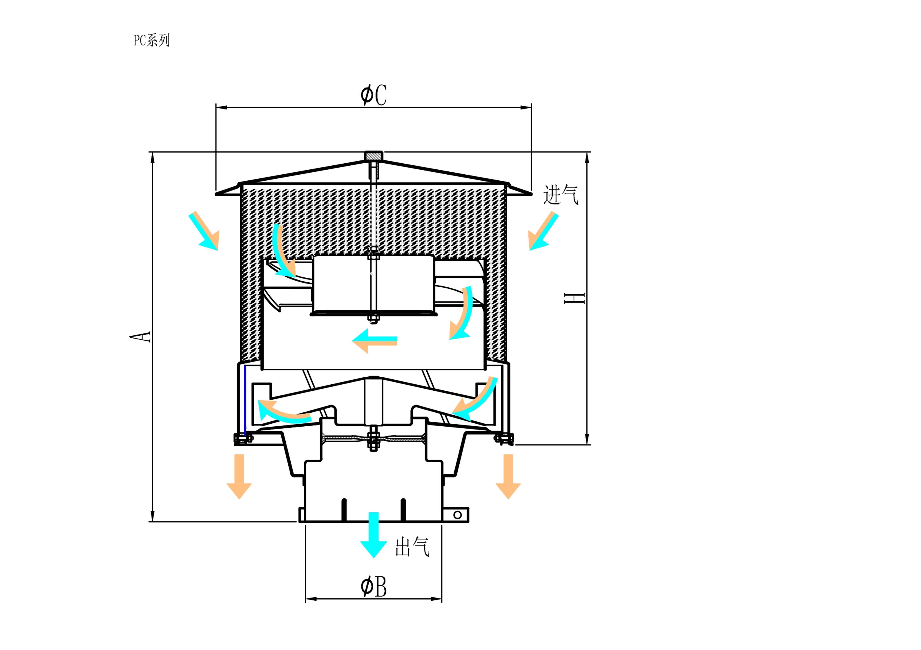
The operational mechanism of a cyclonic engine intake separator is rooted in fluid dynamics. Incoming air enters the unit and is forced to spin. This rotation is achieved either via static vanes that angle the airflow or through a system-driven, free-spinning rotor. As the air spins, it creates centrifugal force. This force drives heavier particles outward toward the unit's outer wall, separating them from the clean air stream that continues down the center into the intake pipe.
Mechanical variations exist between different designs. Fixed-vane or static cyclonic separators have no moving parts. They are highly durable and resist mechanical wear, making them ideal for extremely abrasive environments like rock quarries. Active, air-driven rotor designs use the incoming air to spin a rotor, which actively ejects debris. While highly efficient at lower speeds, these rotors can suffer from abrasive erosion over time if exposed to heavy silica loads, requiring periodic replacement of the bearing and rotor assembly.
Debris discharge methods vary across different precleaner designs, each with specific efficiencies and maintenance requirements.
The separation efficiency curve of a centrifugal unit is highly dependent on particle density. These units achieve high efficiency, often exceeding 90%, for high-density silica, dirt, and metal particulates. The mass of these particles ensures they are easily thrown to the outer walls by centrifugal force. This efficiency drops significantly for lightweight debris. Agricultural chaff, engine soot, or coal dust lack the necessary mass to break free from the air stream's aerodynamic drag.
Particle shape factor affects the separation trajectory inside the cyclonic chamber. Sphericity versus aerodynamic drag plays a major role. A perfectly spherical, dense particle travels predictably to the outer wall. A flat, fibrous, or irregular particle experiences higher aerodynamic drag. The air stream tends to carry these irregular particles along, preventing them from reaching the ejection ports and allowing them to pass into the primary filter. This is why centrifugal units are not recommended for lint or textile dust applications.
Centrifugal systems deliver exceptional performance in environments dominated by sand, gravel dust, and silica. Earthmoving and mining operations generate massive quantities of these dense particulates. The high mass of these materials allows for maximum separation efficiency. The centrifugal force easily overpowers the aerodynamic drag, ejecting the abrasive dirt before it can blind the primary filter media. In a rock quarry, a loader without a precleaner might plug a filter in 50 hours; with a properly sized centrifugal unit, that same filter can last 500 hours.
Industry performance data, based on ISO 5011 inlet air cleaning equipment testing standards, validates this efficiency. Under ISO 5011 testing with coarse test dust, properly sized centrifugal units consistently demonstrate separation efficiencies above 90%. This massive reduction in dust loading directly translates to extended operational hours for heavy machinery in severe environments, keeping equipment running and out of the maintenance bay.
Mixed loads present unique challenges in the field. Agriculture and forestry environments often combine heavy dirt with lightweight leaves, sawdust, seed pods, or crop chaff. While the centrifugal unit easily handles the dirt, the lightweight organics behave differently. Fibrous materials can enter the cyclonic chamber and fail to eject, getting caught in the internal geometry.
This creates a significant risk of screen blinding and housing choking. Fibers wrap around static vanes or jam free-spinning rotors. When the internal passages choke, airflow restriction spikes, and separation efficiency plummets. The engine is then forced to pull air through a restricted, debris-filled chamber, which can collapse the primary filter if the restriction gets high enough.
In these mixed environments, a standard dust separation precleaner requires additional protection. Installing a physical pre-screen, rain cap, or specialized debris guard helps filter out low-density organics before they enter the centrifugal processing chamber. This multi-stage approach protects the cyclonic mechanism from fibrous jams while allowing it to process the heavy dirt effectively.
Technical limitations become apparent when dealing with soot, exhaust carbon, and wet mud. These materials fail to separate efficiently. Soot and carbon are ultra-fine and have extremely low mass. They follow the air stream directly into the primary filter. Wet mud presents a different problem. Moisture causes dust to agglomerate and stick to surfaces rather than ejecting smoothly out of the discharge ports.
There is a high risk of mud-packing inside the centrifugal bowl in high-humidity, high-dust environments. Coastal construction sites or operations in wet clay soils frequently encounter this issue. The damp dust enters the spinning chamber, hits the outer wall, and sticks. Over time, this mud packs tightly, altering the internal geometry of the precleaner and destroying its ability to separate debris. Operators in these conditions must manually clean the bowls daily.
Chemical degradation risks also exist. Operations handling chemical fertilizers or corrosive salts must choose their precleaner materials carefully. Corrosive particulates processed through metal housings cause rapid rusting and structural failure. In these specific applications, composite or heavy-duty plastic precleaner housings are necessary to resist chemical attack and maintain structural integrity over the life of the machine.
Maintenance intervals and restriction profiles differ wildly between centrifugal units and basic rain caps or mesh screens. Basic screens offer minimal protection, only stopping large debris like leaves or rocks. They require frequent manual cleaning. Centrifugal units are largely self-cleaning, ejecting dust continuously or via automated valves, significantly extending maintenance intervals and reducing operator intervention.
Static screens suffer from progressive restriction buildup. As debris covers the mesh, the open area decreases, and airflow restriction rises steadily. This starves the engine of air. Centrifugal systems maintain a relatively constant restriction level. Because they actively eject the debris, the internal air passages remain clear, ensuring consistent airflow to the engine regardless of how much dust they process.
Exhaust-scavenged systems offer continuous debris removal by using exhaust vacuum to pull dust from the precleaner. The trade-offs involve installation complexity and cost. Scavenged systems require routing steel tubing from the intake precleaner to a specialized venturi in the exhaust stack. This installation is complex, requires modifying the exhaust system, and carries a higher initial hardware cost.
Scavenged systems handle higher volumes of continuous particle loads exceptionally well. They are preferred in the most extreme mining conditions where standard top-spin centrifugal units might become overwhelmed. The active vacuum ensures that even massive dust clouds are processed and ejected efficiently without relying solely on the internal spinning action of the intake air.
Multi-cyclone block panels use dozens of small cyclonic tubes arranged in a grid. These are commonly used in military tanks and massive mining haul trucks. Single-stage centrifugal precleaners are compact and mount directly to the intake pipe. Multi-cyclone panels require significant space and complex housing structures integrated into the vehicle's bodywork.
The airflow capacity of a multi-cyclone panel is massive, designed for huge engines drawing thousands of CFM. Their fractional efficiency curves are very high, as the small diameter of each individual tube generates immense centrifugal force. Single-stage centrifugal units offer a more practical, cost-effective solution for standard heavy equipment, providing excellent efficiency without the extreme space constraints and engineering requirements of block panels.
A conceptual trade-off exists between airflow restriction and separation efficiency. Achieving higher separation efficiency requires higher air velocity inside the precleaner to generate sufficient centrifugal force. This increased velocity increases the initial intake restriction. The system must be carefully balanced to provide adequate cleaning without choking the engine. You cannot simply install the smallest unit to get the fastest spin; you will destroy the engine's performance.
Calculating acceptable restriction limits requires consulting OEM engine specifications. Every engine has a maximum allowable intake restriction, usually measured in inches of water column (in. H2O). Exceeding this limit leads to power loss, increased fuel consumption, and elevated exhaust temperatures. You must ensure the combined restriction of the precleaner, the clean piping, and a new primary filter stays well below the OEM maximum limit, leaving room for the filter to load with dust over time.
Excessive restriction causes severe downstream effects. It disrupts Diesel Particulate Filter (DPF) regeneration cycles by altering the air-to-fuel ratio, leading to increased soot production and frequent active regenerations. High intake vacuum puts immense stress on turbocharger bearings, potentially causing premature turbo failure and pulling oil past the seals into the charge air cooler.
Realistic ROI calculations rely on hard data from the field. Implementing a proper precleaner reduces primary filter purchasing frequency. It decreases the labor hours spent on field filter changes. Most importantly, it eliminates unscheduled downtime caused by dusted engines or suddenly plugged filters in the middle of a production shift.
To calculate the payback period, follow these steps:
The most common implementation failure in the field is sizing the precleaner to match the intake pipe diameter rather than the engine's actual CFM requirements. Pipe diameter does not dictate airflow volume. Sizing strictly by pipe diameter frequently leads to severe performance issues and complete failure of the pre-filtration strategy.
Under-sizing a precleaner forces too much air through a small unit. This leads to air starvation, high restriction, increased fuel consumption, and premature engine wear. The engine struggles to breathe, performance drops noticeably, and the high velocity can actually pull separated dust back into the clean air stream.
Over-sizing is equally detrimental. If the unit is too large for the engine's airflow, the air velocity inside the chamber drops. This results in insufficient air velocity to create the necessary centrifugal force. The heavy dirt simply falls through the unit without spinning, rendering the cyclonic engine intake separator entirely useless. The dust goes straight into the primary filter.
You must calculate the actual engine CFM to select the correct unit. The standard formula is: CFM = (Displacement in CID x RPM x Volumetric Efficiency) / 3456. The Volumetric Efficiency (VE) constants vary by engine type. Use 0.85 for naturally aspirated engines. For modern turbocharged and aftercooled diesel engines, the VE ranges from 1.5 to over 3.0, depending on boost pressure. Always size the precleaner so the engine's operating CFM falls squarely in the middle of the precleaner's rated airflow range.
Centrifugal units add physical weight to the end of the intake piping. Heavy-duty metal units require reinforcing the intake piping. Failure to support this weight leads to vibration-induced cracking of mounting brackets, intake tubes, and equipment hoods. Always ensure robust, structural mounting solutions are utilized, using rubber isolators if necessary to dampen engine vibration.
Correct orientation requirements dictate performance. Some units are designed exclusively for vertical mounting, relying on gravity to assist with debris ejection through a bottom vacuator valve. Others can handle horizontal mounting. Always verify the manufacturer's specifications regarding orientation to ensure gravity does not negatively affect the specific discharge design. Mounting a gravity-dependent unit sideways guarantees failure.
Routine visual inspections are mandatory. Maintenance personnel must check the ejection ports for blockages caused by mud or fibrous debris. Vacuator valves must be inspected for dry rot, tearing, or inversion. Rotor assemblies in active units should be checked to ensure they spin freely without bearing noise or excessive play. A seized rotor turns the precleaner into a massive restriction point.
A: The fractional efficiency curve shows separation efficiency remains near 90% or higher for particles larger than 20 microns. Efficiency drops sharply for PM10 (under 10 microns) and PM2.5 particulates. At these smaller sizes, the particle mass is insufficient to overcome aerodynamic drag, allowing them to pass through to the primary filter.
A: Yes, all filtration devices add some restriction, typically measured in inches of water column. Correct CFM sizing mitigates this performance loss to negligible levels. A properly sized unit creates enough velocity for separation while keeping total restriction well below the OEM maximum limits.
A: Yes, centrifugal force effectively ejects heavier water droplets and snow, allowing the unit to act as an excellent weather cap. You must avoid operating in heavy, freezing slush conditions, as accumulating ice can freeze rotor blades or block ejection ports, causing severe restriction.
A: Multiply your engine's displacement in cubic inches by its maximum rated RPM, then multiply by the volumetric efficiency factor, which is typically 2.0 to 3.0 for a modern turbo diesel. Divide that total by 3456. This provides the target operating CFM range needed to select the correct precleaner size.
A: The most common causes include over-sizing the unit, which leads to low internal air velocity and poor separation. Other culprits include structural leaks in downstream ductwork, worn-out or missing vacuator valves, or operating in an environment dominated by ultra-fine soot that bypasses centrifugal forces.
