
Views: 0 Author: Site Editor Publish Time: 2026-08-15 Origin: Site


Wheel loaders operating in high-debris environments—such as mining, forestry, landfills, farming, and aggregate processing—face accelerated engine wear and exorbitant primary filter replacement costs due to particulate ingestion. An air pre-cleaner acts as the engine's primary mask, filtering out up to 98% of airborne dust and heavy impurities before they ever reach the internal air filter. While installing an air pre-cleaner is standard practice, selecting the wrong size introduces severe mechanical risks. An undersized unit creates excessive intake restriction (starving the engine and increasing exhaust temperatures), while an oversized unit fails to generate the necessary centrifugal force to expel dust, rendering it useless. Determining the correct size requires moving beyond generic machine weight classes and calculating precise engine airflow requirements (CFM). This guide provides the engineering formulas, technology comparisons, industry model benchmarks, and implementation frameworks necessary to specify the exact pre-cleaner for your fleet.
Defining a successful installation requires looking at the hard numbers from the field. You want to achieve maximum dust separation efficiency, capturing 85 to 98 percent of particles before they hit the main filter housing. At the same time, you must maintain intake restriction well below the OEM maximum allowable limit. This limit is usually measured in inches of water. Balancing these two factors dictates the operational success of your machine. When you get this balance right, the engine breathes easily while remaining protected from abrasive contaminants that cause premature cylinder wear.
Different environments demand specific pre-cleaner configurations. Landfill waste presents large, unpredictable debris like plastic bags and paper scraps that can easily blind a standard intake screen. Agricultural chaff is light, sticky, and prone to clogging static components. Construction dust is highly abrasive. Mining silica is exceptionally fine and destructive to piston rings. Mapping the right technology to these distinct machinery environments prevents premature engine failure. You cannot take a unit designed for logging and expect it to perform flawlessly in a rock quarry.
The mechanical consequences of undersizing an air pre-cleaner for wheel loader are severe and immediate. When you restrict intake air, you starve the engine of the oxygen required for complete combustion. This leads to increased fuel consumption and a noticeable drop in horsepower. Operators will complain about sluggish response and significant turbo lag. Furthermore, running rich fuel mixtures creates heavy soot. This soot quickly overloads the Diesel Particulate Filter (DPF) and the Exhaust Gas Recirculation (EGR) system, leading to costly emissions system repairs and forced regenerations that halt production.
Oversizing presents a different, yet equally damaging problem. Centrifugal separation relies entirely on physics and fluid dynamics. A pre-cleaner requires specific air velocity to spin the impeller or force air along static vanes. If the unit is too large for the engine's airflow, the velocity drops significantly. Insufficient velocity means dust simply bypasses the separation mechanism. It flows straight through the housing and impacts the primary filter directly. You end up carrying extra weight on the intake stack without gaining any filtration benefits.
To illustrate the impact of proper sizing, consider the restriction limits set by major engine manufacturers. Most heavy-duty diesel engines have a maximum allowable intake restriction of 25 to 30 inches of water for a dirty filter, and often limit clean filter restriction to 10 to 15 inches of water. Adding an undersized pre-cleaner can immediately add 8 to 10 inches of restriction right out of the box. This leaves almost no room for the primary filter to do its job before the restriction indicator trips. Proper sizing ensures the pre-cleaner adds minimal restriction, usually between 1 and 3 inches of water, preserving the functional lifespan of the primary paper element.
Engine airflow dynamics dictate your sizing strategy. Three main variables control air consumption. These are engine displacement, maximum governed RPM, and volumetric efficiency. Displacement is measured in liters or cubic inches. RPM represents the engine speed under full load. Volumetric efficiency measures how effectively the cylinders fill with air during the intake stroke. Understanding these variables is the first step in moving away from guesswork and toward engineered solutions.
You can determine the exact airflow using a standard mathematical framework. For naturally aspirated engines, the formula is straightforward. Multiply the engine displacement in cubic inches by the maximum RPM. Divide that total by 3456. The resulting number is your Base CFM. This establishes the baseline airflow requirement for your machine. For example, a 500 cubic inch engine running at 2200 RPM requires approximately 318 CFM of air. This is a simple calculation, but it forms the foundation of your equipment specification.
Most modern wheel loaders use forced induction. Turbocharged and intercooled engines pack more air into the cylinders to generate higher horsepower from smaller displacements. You must adjust your base calculation to account for this boost pressure. Forced induction increases volumetric efficiency significantly. You typically need to apply a multiplier of 1.5 to 2.0 to your Base CFM. The exact multiplier depends on the manifold absolute pressure generated by the turbocharger. A heavily boosted engine might require double the airflow of a naturally aspirated engine of the same physical size.
Operating conditions also influence air density and total airflow requirements. High altitude operations experience thinner air. Extreme ambient temperatures change the air volume entering the intake. Thinner air requires the turbocharger to work harder and spin faster to achieve the target manifold pressure, altering the actual CFM drawn through the intake stack. You must account for these variables to ensure your sizing margins remain accurate across different job sites. If you size a loader engine precleaner for sea level and ship the machine to a high-altitude mine, the unit may underperform or cause excessive restriction.
Let us look at a practical calculation for a mid-sized wheel loader. Assume the machine has an 8.8-liter engine. First, convert liters to cubic inches by multiplying by 61.02. This gives us roughly 537 cubic inches. The maximum governed engine speed is 2100 RPM. Multiplying 537 by 2100 gives 1,127,700. Dividing by 3456 yields a base CFM of 326. Because this is a modern turbocharged diesel, we apply a conservative multiplier of 1.8. The final requirement is 587 CFM. You must select a pre-cleaner where 587 CFM falls squarely in the middle of its operating efficiency band.
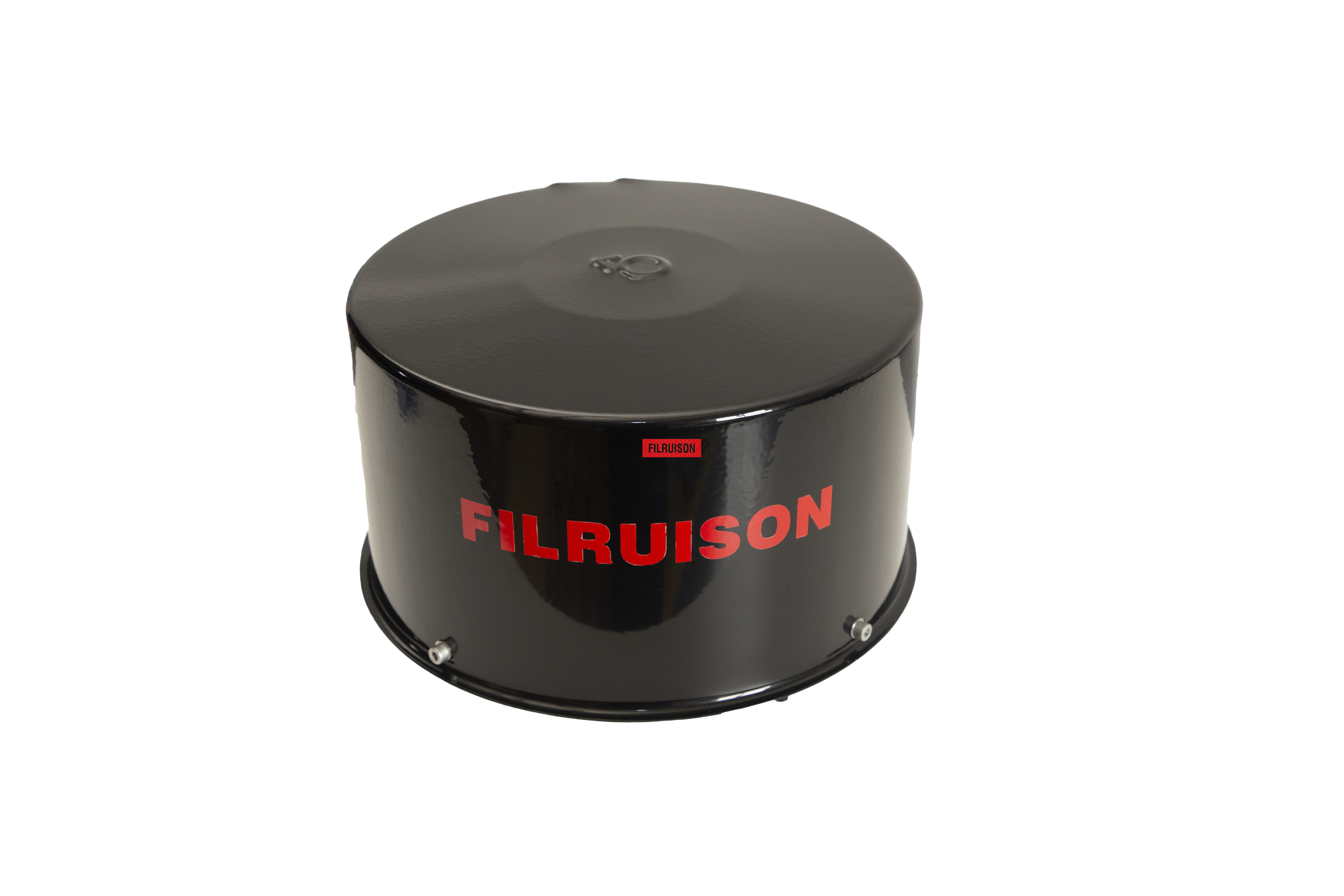
Selecting the right separation mechanism is critical for long-term reliability. Different designs handle specific types of debris better than others. You must match the technology to your primary operating environment. A mismatch here will result in clogged units, broken rotors, or bypassed dust.
Active turbine units utilize incoming air to spin an internal rotor. This spinning motion generates strong centrifugal force. The force ejects heavy debris outward through designated discharge ports. They are excellent for mixed debris environments and heavy construction. They offer reliable self-cleaning capabilities, meaning operators do not need to empty bowls manually. However, they are highly sensitive to CFM ranges. Models are strictly tiered, covering specific bands like 100-300 CFM or 300-700 CFM. If you fall outside these bands, the rotor will not spin fast enough to eject the dirt.
Static designs use stationary angled vanes to create a vortex. This vortex deposits dust into a collection bowl or ejects it via a one-way rubber valve. They are ideal for fine dust environments like agriculture or dry dirt. Lacking moving parts, they will not seize when exposed to sticky chaff or wet mud. They generally offer a slightly wider acceptable CFM operating band compared to active turbines. If using a collection bowl, they require frequent visual inspection and manual dumping by the operator.
Scavenged systems connect the pre-cleaner directly to the exhaust stack via a venturi tube. They use high-speed exhaust gas velocity to pull dust out of the intake stream. This creates a powerful vacuum effect that continuously evacuates the pre-cleaner housing. They are best suited for extreme high-dust environments like mining and heavy earthmoving. Zero-maintenance ejection is a major advantage here. Sizing requires precise matching of both intake CFM and exhaust flow characteristics to maintain the necessary venturi vacuum without creating excessive exhaust backpressure.
| Technology Type | Primary Mechanism | Best Operating Environment | Sizing Sensitivity |
|---|---|---|---|
| Active Turbine | Internal spinning rotor | Mixed debris, heavy construction | High (strictly tiered CFM bands) |
| Static / Vane-Style | Stationary angled vanes | Fine dust, agriculture | Moderate (wider CFM band) |
| Scavenged Exhaust | Exhaust venturi vacuum | Extreme dust, mining | Very High (matches intake and exhaust) |
When evaluating these technologies, you must also consider the physical footprint. Active turbines tend to be taller and heavier due to the internal bearings and rotor assembly. Static vane units can often be designed with a lower profile, making them suitable for machines with visibility constraints. Scavenged systems require additional plumbing, including steel tubing routed from the intake to the exhaust, which adds complexity to the installation and requires careful routing to avoid hot engine components.
The heavy equipment industry utilizes established sizing frameworks to ensure optimal performance. Manufacturers segment their product lines into distinct, non-overlapping models. You will typically see coverage ranging from 100 to 1100 CFM. These are often categorized as Model 24, Model 35, Model 46, and Model 68 equivalents. This strict segmentation ensures the air velocity remains high enough for effective separation across different engine sizes.
Compact to mid-size loaders generally fall into the 100 to 400 CFM range. For these machines, you need lightweight, low-profile units. Focus on minimizing added vibration to smaller intake stacks. A heavy unit can cause the intake pipe to crack over time, leading to unfiltered air entering the engine directly. Maintaining operator visibility over shorter hoods is also a priority when selecting a wheel loader intake dust separator for smaller equipment. You do not want a massive dome blocking the view of the bucket edge.
Heavy-duty and mining loaders demand massive airflow, often exceeding 400 to 1100+ CFM. These massive displacement engines require dual-stage or multi-rotor units. In some extreme cases, fleet managers must decide between manifolding multiple smaller pre-cleaners together or installing one massive central unit. Manifolding can sometimes offer better separation efficiency by keeping air velocity high across multiple smaller rotors, rather than relying on one giant rotor that takes longer to spool up during sudden acceleration.
You must also weigh the trade-offs between OEM and aftermarket integration. Proprietary systems offer guaranteed fitment but often come with a premium price tag and limited availability in remote areas. Universal aftermarket solutions provide excellent performance and flexibility across mixed fleets. Evaluate your warranty implications before making a switch. Check adapter availability to ensure a tight, leak-free seal on the intake pipe. Long-term parts availability for replacement rotors, bearings, or collection bowls is crucial for minimizing downtime.
| Loader Size Category | Typical CFM Range | Common Industry Model Equivalent | Primary Installation Concern |
|---|---|---|---|
| Compact / Utility | 100 - 250 CFM | Model 24 | Vibration on small intake pipes |
| Mid-Size Construction | 250 - 500 CFM | Model 35 | Operator visibility over hood |
| Heavy-Duty / Quarry | 500 - 800 CFM | Model 46 | Handling high-velocity abrasive dust |
| Large Mining | 800 - 1100+ CFM | Model 68 or Dual Setup | Managing massive airflow without restriction |
Adding weight to the top of an intake stack introduces structural risks. Metal fatigue on the intake pipe is a common failure point in the field. The added top-weight of the pre-cleaner amplifies vibrations from the engine and rough terrain. You can mitigate this by installing heavy-duty support brackets that tie the intake pipe to a solid point on the chassis or hood structure. Use reinforced silicone hump hoses to absorb vibration and allow for slight movement between the engine and the fixed intake stack. Keep the unit mounted as close to the hood line as possible to reduce leverage.
Hood clearance and operator visibility are critical safety factors. Evaluate the physical dimensions of appropriately sized units before installation. A massive cylindrical unit might obstruct the operator’s line of sight to the bucket or attachments, creating a safety hazard on busy job sites. If visibility is compromised, select low-profile dome designs. These provide the necessary CFM capacity without creating dangerous blind spots. Always perform a visibility check from the operator's seat before finalizing the installation.
Upward-facing intakes present water ingestion risks. Rain or melting snow can enter the system if not properly managed. Analyze the potential for moisture ingress in your specific climate. Ensure the selected pre-cleaner features adequate water drain ports. The unit must be rated for high-moisture environments to prevent water from soaking the primary paper filter. A wet paper filter will immediately restrict airflow and can collapse under the vacuum of the engine.
Maintaining separation efficiency requires strict preventative maintenance protocols. You cannot install these units and forget about them.
An air pre-cleaner for a wheel loader is a precisely engineered component that dictates the lifespan of your engine. It must match your engine's specific airflow characteristics to function correctly. Proper sizing protects your engine, reduces consumable costs, and maximizes machine uptime in the harshest environments.
A: An oversized unit will not experience enough air velocity to create the centrifugal force needed to separate dust. The debris will simply pass through the unit and prematurely clog your primary air filter.
A: You can calculate base CFM by multiplying engine displacement (in cubic inches) by maximum RPM, and dividing by 3456. For turbocharged engines, you must multiply this base number by the engine's volumetric efficiency ratio (typically 1.5 to 2.0).
A: Yes. Every pre-cleaner adds some level of intake restriction. If the unit is undersized, this restriction will exceed OEM limits, leading to power loss, higher exhaust temperatures, and increased fuel consumption.
A: When properly sized for the engine and operating environment, a high-efficiency pre-cleaner serves as the first line of defense, removing up to 98% of incoming debris and extending primary filter life by up to three times.
A: Yes. Higher altitudes mean thinner air, which forces the turbocharger to work harder to achieve the necessary manifold pressure. This can alter the actual volume of air drawn through the intake, requiring adjustments to your CFM calculations.
