
Views: 0 Author: Site Editor Publish Time: 2026-10-27 Origin: Site


Picture this scenario. You operate a heavy-duty wheel loader through a thick cloud of abrasive silica dust. Or perhaps you navigate a modified overland vehicle across a dry desert trail. The immediate concern for any equipment operator in these harsh conditions is catastrophic internal damage. Investing in an Engine Air Pre Cleaner is a highly effective strategy for extending equipment life. Simply bolting the unit onto the nearest pipe is not enough. A poor location inadvertently sucks in a higher concentration of debris. Worse, it can severely restrict vital oxygen flow to the combustion chamber.
This comprehensive guide explores exactly where your filtration unit should sit to maximize its efficiency. Understanding how to determine the optimal vertical placement helps you bypass heavily contaminated air pockets. This ensures peak engine performance. Whether you are a fleet manager analyzing maintenance intervals or a DIY mechanic optimizing an off-road rig, applying standardized fluid dynamics principles protects your machinery. It maximizes long-term reliability.
Avoid Heavy Contamination: The filtration unit must sit above the dense concentration of particulate matter kicked up by tires, tracks, and cooling fans.
Optimal Vertical Placement: Sitting the device at the roofline or cab level is generally the most effective way to capture clean ambient air.
Direct Path to Intake: Position the unit to allow the shortest and straightest path to the main intake manifold. This prevents airflow restriction.
Secure Hardware: Proper mounting brackets and vibration-resistant hardware are essential. They keep the system stable in rugged environments.
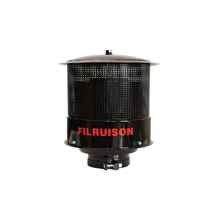
Before determining where the device should sit, we must understand its mechanical function. A pre-filtration unit operates primarily on the principle of centrifugal force. Ambient air is drawn into the housing. Specially angled static vanes or high-speed spinning rotors force the incoming air into a rapid circular motion. Dirt, crop chaff, snow, and gravel dust are heavier than the air itself. Rotational velocity drives these heavier particles toward the outer walls of the housing. They are safely ejected through a discharge louver.
Field data and engineering tests indicate that a properly functioning separator ejects up to 90 percent of heavy particulate matter. This happens before the debris ever reaches the primary pleated paper filter. Consequently, this significantly reduces the maintenance burden. It minimizes downtime and protects internal cylinders from premature wear caused by silica ingress.
The physical location of the separator directly dictates its operational efficiency. Centrifugal separation requires a specific volume and consistent velocity of air to function correctly. The unit might sit in an area of extreme aerodynamic turbulence. Or it might sit where the dirt concentration exceeds its processing capacity. In these cases, efficiency drops dramatically. An improperly seated device works much harder to process highly contaminated air. Ultimately, it provides significantly less protection. Therefore, placement is a critical engineering decision rather than a matter of convenience.
In off-highway and industrial applications, the most critical rule of installation is avoiding the localized envelope of highly contaminated air. This turbulent area surrounds a moving vehicle. In mechanical engineering circles, this turbulent area is widely referred to as the Dust Zone. It typically extends from ground level up to the lower hood or windshield area. Heavy tires, metal tracks, and engine cooling fans actively churn up the highest concentration of dirt and debris here.
Depending on soil moisture and vehicle speed, the particulate density in this lower area is massive. It can be hundreds of times higher than the ambient air just a few feet above it. A separator sitting deep inside this zone is forced to process an incredibly dense mixture of grit. This overwhelming volume can easily block the ejection ports.
The aerodynamic profile of a tractor or haul truck pushes a massive bow wave of air over the hood as it moves forward. To function optimally, the intake point must sit completely outside this turbulent air pocket. Elevating the intake above the vehicle boundary layer allows the system to draw in relatively clean air. Specifically, this strategic positioning drastically reduces the initial dirt load the centrifugal mechanism has to process.
Equipment managers generally choose between hood-level and cab-level placement when selecting a mounting location. Hood-level installations are easier to execute and require shorter piping. However, they frequently place the intake directly inside the upper limits of the contamination cloud. In contrast, extending the Installation Height to the roofline or above the cab is highly recommended for extreme environments. Open-pit mining, large-scale agriculture, and deep-desert overlanding require this elevation. At cab level, the air is significantly cooler, cleaner, and much less turbulent.
Placement Strategy | Air Quality Captured | Aerodynamic Turbulence | Installation Complexity | Best Application |
|---|---|---|---|---|
Hood Level | Moderate to Poor | High boundary layer turbulence | Low. Requires minimal piping. | Light construction, highway transport |
Cab / Roof Level | Excellent. Cool and dense. | Low. Sits above the bow wave. | Medium. Requires vertical extension. | Agriculture, heavy mining, off-road |
Remote Snorkel | Excellent | Minimal | High. Requires structural brackets. | Deep water wading, severe dust convoy |
A higher placement undeniably yields cleaner air. However, operators must balance this aerodynamic advantage with practical physical limitations. The vertical extension must not exceed safe clearance levels for the operating environment. Agricultural equipment must navigate under low-hanging tree branches in orchards. Highway construction machinery must safely clear facility doors and tunnel structures. Carefully measure the maximum vertical clearance of your typical operational routes prior to finalizing the setup. This prevents catastrophic impacts that could tear the entire assembly from the vehicle.
Capturing clean air is only half of the equation. Delivering that air efficiently to the combustion chamber is equally critical. The physics of fluid dynamics dictate that every bend and curve introduces airflow restriction. Engineers refer to this as a pressure drop. Therefore, the device should sit in a location that allows for the shortest and straightest connection possible to the vehicle main Air Inlet.
Air forced to navigate a sharp 90-degree elbow joint creates internal turbulence. This slows down the velocity and forces the turbocharger to work harder to pull in oxygen. The accumulated restriction from multiple bends can negate the benefits of the clean air. Ultimately, this leads to reduced horsepower and poor fuel economy.
The diameter of the intake piping is a vital factor beyond the physical path. Operators must perfectly match the separator outlet diameter to the factory housing. Using piping that is too narrow creates a severe bottleneck. It chokes the engine and starves it of oxygen. Conversely, using piping that is unnecessarily wide causes the air velocity to plummet. The centrifugal mechanism relies on a specific airflow speed to spin the internal vortex effectively. Moving air too slowly causes dust separation efficiency to fail.
Filtration devices generally sit on a vehicle in two primary ways. Direct-to-snorkel integration involves clamping the unit directly onto the top of an existing vertical intake pipe. This method is highly efficient for smaller tractors as it requires zero additional bends. Remote placement involves securing the housing to a stable structural component like a heavy-duty roll cage or cab roof. Flexible hosing then runs down to the engine bay. Massive industrial units often require this because they are too heavy for standard aluminum tubes to support.
Heavy machinery and off-road rigs produce intense low-frequency vibrations. This causes structural metal fatigue over time. Utilizing robust Pre Cleaner Mounting hardware is absolutely essential. The leverage exerted by a heavy polymer or steel unit sitting at the end of a long pipe is immense when bouncing over jagged rock formations. Incorporate rubber vibration isolators between the bracket and the vehicle frame to absorb harsh impacts. Furthermore, utilize high-torque stainless steel T-bolt clamps. Standard worm-gear clamps easily shake loose and create a dangerous vacuum leak.
Recent developments across the heavy-duty machinery sector reveal a clear paradigm shift in intake system design. Modern diesel engines must meet stringent global emission standards like Tier 4 Final and Stage V. These engines feature incredibly tight internal tolerances and advanced turbocharging systems. They demand higher volumes of ultra-clean air than ever before. Consequently, equipment manufacturers and fleet operators no longer treat pre-filtration placement as an aftermarket afterthought.
There is a strong push toward aerodynamically optimized factory-integrated placements. Engineers increasingly utilize computational fluid dynamics CFD to map airflow over the machinery cab. This ensures the intake point sits perfectly within the cleanest ambient air streams. This proactive science-backed approach significantly reduces the total cost of ownership. It extends service intervals in increasingly harsh particulate-heavy operational environments.
Allowing the intake to sit in the path of the vehicle exhaust stack is a detrimental error. Drawing in hot sooty exhaust gases severely reduces combustion efficiency because hot air is less dense. Furthermore, the oily soot from diesel exhaust quickly coats the inside of the centrifugal chamber. This creates a sticky residue that traps dirt and clogs the entire system far faster than dry dust alone.
These devices are explicitly designed to process external ambient air. Sitting the unit inside the engine bay defeats its primary purpose entirely. The air under the hood is stagnant and heavily laden with micro-debris pulled in by the radiator fan. It is also superheated by the engine block. Engines require cool dense air. An under-hood placement starves the system of both cleanliness and density.
Orientation matters greatly for specific directional or ram-air style units. A directional scoop pointed backward creates a low-pressure vacuum behind the intake. The engine must fight against aerodynamic drag just to breathe. Directional units should generally face forward to capitalize on the ram-air effect. This actively pushes clean air into the manifold.
Every engine has specific cubic feet per minute CFM airflow requirements. Lengthening the pipe excessively to achieve a higher roofline placement alters the CFM delivery. Ignoring the maximum piping length or diameter recommendations leads to severe airflow restriction. Always consult the technical specifications to ensure the chosen spot does not exceed the allowable pressure drop.
Relying on cheap plastics or thin aluminum strapping to secure a heavy device is a recipe for catastrophic failure. Flimsy mounts snap under the stress of off-road bouncing or heavy excavation work. If the housing falls off or cracks the intake pipe, the engine immediately ingests massive amounts of unfiltered dirt. This leads to rapid cylinder scoring.
Choosing the correct spot requires matching the product capabilities to your specific machine. Below are actionable standards for different equipment categories.
The primary airborne contaminants in agriculture are chaff, crop husks, and dry topsoil. Tractors move relatively slowly and sit in a lingering cloud of their own making. Tall vertical stacks extending well above the hood are strictly necessary. This elevated placement avoids the dense organic material generated by harvesting headers. For these applications, integrating a high-efficiency centrifugal unit like the KC Series ensures optimized flow dynamics. The KC Series handles heavy chaff loads without clogging the ejection ports.
Loaders, excavators, and haul trucks face severe abrasive silica dust. The separator should sit as far back from the front bucket as possible. Mounting it high behind the cab is a proven strategy. This location prevents the unit from swallowing the massive plume of dust created every time the bucket dumps dry earth. For extreme environments demanding higher volumetric processing, industrial-grade units like the PC24 model provide superior separation efficiency. The rugged construction of the PC24 withstands the harsh impacts typical in mining operations.
Fine trail dust from leading convoy vehicles and water ingress during river crossings are the primary threats for 4x4 vehicles. The standard practice involves integrating the device with an A-pillar snorkel. The unit should sit just above the roofline facing forward. This keeps the intake completely out of the wheel-well dust wake. It also remains high enough to prevent hydro-locking during deep wading scenarios.
An external air separation device is an incredibly powerful tool for extending equipment life and reducing maintenance costs. However, its success depends entirely on intelligent fluid-dynamics-based placement. Always elevate the unit above the heavy contamination clouds. Optimize the vertical height for safe environmental clearance. Ensure a straight unrestricted path to the intake manifold. Securing the system with heavy-duty hardware and avoiding common installation pitfalls guarantees that your engine breathes the cleanest air possible. Take the time to inspect your current air intake setup today. If you need to upgrade your filtration strategy, explore the professional-grade solutions at Sykingtech to find the perfect aerodynamic match for your specific machine.
No. It should sit strictly outside the engine bay to capture cool ambient air. Placing it under the hood forces the engine to ingest hot stagnant air. This reduces air density, lowers engine power, and defeats the purpose of an external pre-filtration system.
Yes, indirectly. An optimal vertical placement ensures the engine receives a continuous supply of clean dense air without restriction. Unrestricted airflow helps the engine maintain optimal air-to-fuel ratios. This ensures efficient fuel combustion and prevents the drop in fuel economy associated with clogged filters.
It should sit as close as practically possible while still remaining outside the heavy contamination zone. Shorter piping reduces airflow restriction and pressure drops. This allows the turbocharger and engine to breathe freely without excessive suction effort.
A loose mount causes the device to vibrate violently against the vehicle body. Structural stress cracks the air intake piping or loosens the clamps. This creates a vacuum leak that allows unfiltered abrasive dust to bypass the filtration system entirely and enter the engine cylinders.
Most high-quality modern units are engineered to eject rain and moisture using the exact same centrifugal force that ejects dust. As long as the unit is mounted correctly according to OEM specifications, you do not need to move or cover it during wet weather conditions.
You must determine your engine displacement and maximum RPM. The basic formula involves multiplying the engine displacement in cubic inches by the maximum RPM, then dividing by 3456. This gives you the baseline CFM. Ensure your chosen mounting location allows for piping wide enough to support this CFM without causing a severe pressure drop.
No. A pre cleaner acts as the first line of defense. It removes up to 90 percent of the heavy abrasive particles before they reach the factory intake. You must still retain your primary pleated paper filter to capture the microscopic dust particles that pass through the centrifugal stage.
